Infiniti FX35 / FX45. Manual - part 128


  Index      Infiniti     Infiniti FX35 / FX45 (S50) - service repair manual 2008 year


Search            


Content   ..  126  127  128  129   ..


Infiniti FX35 / FX45. Manual - part 128


ATC-108

< SERVICE INFORMATION >

HEATER & COOLING UNIT ASSEMBLY

HEATER & COOLING UNIT ASSEMBLY

Removal and Installation

INFOID:0000000001328211

REMOVAL

1.

Use a refrigerant collecting equipment (for HFC-134a) to discharge the refrigerant.

2.

Drain coolant from cooling system. Refer to 

CO-10, "Changing Engine Coolant"

 (VQ35DE) or 

CO-37,

"Changing Engine Coolant"

 (VK45DE).

3.

Remove cowl top cover. Refer to 

EI-23

.

4.

Remove high-pressure pipe 2 mounting clip.

5.

Remove low-pressure flexible hose bracket mounting bolt. Refer to 

ATC-128, "Removal and Installation of

Low-Pressure Flexible Hose"

.

6.

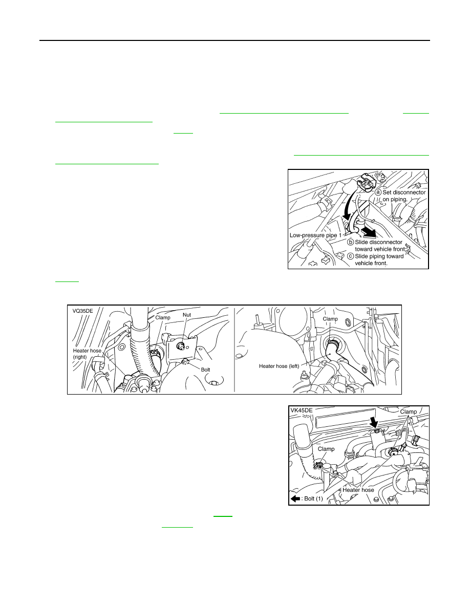
Disconnect low-pressure pipe 1 and high-pressure pipe 2 from
evaporator.

a.

Set a disconnector [high-pressure side (SST: 9253089908), low-
pressure side (SST: 9253089916)] on A/C piping.

b.

Slide a disconnector toward vehicle front until it clicks.

c.

Slide A/C piping toward vehicle front and disconnect it.

CAUTION:

Cap or wrap the joint of low-pressure pipe 1, 2 and high-
pressure pipe 2, 3 with suitable material such as vinyl tape
to avoid the entry of air.

7.

Remove electric throttle control actuator (VQ35DE). Refer to

EM-19

.

8.

Disconnect two heater hoses from heater core.

9.

Remove instrument panel and pad. Refer to 

IP-10

.

10. Remove blower unit. Refer to 

ATC-103

.

RJIA2037E

RJIA2077E

RJIA2041E

HEATER & COOLING UNIT ASSEMBLY

ATC-109

< SERVICE INFORMATION >

C

D

E

F

G

H

I

K

L

M

A

B

ATC

N

O

P

11. Remove mounting nuts and bolts, and then remove instrument stays (left and right side).

12. Remove mounting bolts from heater & cooling unit assembly.

13. Disconnect drain hose.

14. Remove center and side ventilator ducts, defroster nozzle and side defroster ducts. Refer to 

ATC-116,

"Removal and Installation"

.

15. Remove steering column mounting bolts and nut.

16. Remove steering member mounting bolts, nut and harness clips.

17. Remove steering member, and then remove heater & cooling unit assembly.

INSTALLATION

Installation is basically the reverse order of removal.

CAUTION:

• Replace O-rings of low-pressure pipe 1 and high-pressure pipe 2 with new ones, and then apply

compressor oil to it when installing it.

• Female-side piping connection is thin and easy to deform. Slowly insert the male-side piping

straight in axial direction.

• Insert piping securely until a click is heard.
• After piping connection is completed, pull male-side piping by hand to make sure that connection

does not come loose.

• When recharging refrigerant, check for leaks.

RJIA2042E

SJIA1223E

SJIA1656E

ATC-110

< SERVICE INFORMATION >

HEATER & COOLING UNIT ASSEMBLY

NOTE:
• When filling radiator with coolant, refer to 

CO-10, "Changing Engine Coolant"

 (VQ35DE) or 

CO-37, "Chang-

ing Engine Coolant"

 (VK45DE).

• Recharge the refrigerant.

Heater & cooling unit assembly mounting bolt

: 6.8 N·m (0.69 kg-m, 60 in-lb)

Steering member mounting nut and bolt

: 12 N·m (1.2 kg-m, 9 fl-lb)

Steering column mounting nut and bolt

: 16.7 N·m (1.7 kg-m, 12 fl-lb)

HEATER & COOLING UNIT ASSEMBLY

ATC-111

< SERVICE INFORMATION >

C

D

E

F

G

H

I

K

L

M

A

B

ATC

N

O

P

Disassembly and Assembly

INFOID:0000000001328212

1.

Heater pipe grommet

2.

Heater core

3.

Heater pipe cover

4.

Aspirator

5.

Aspirator hose

6.

Air mix door motor (driver side)

7.

Air mix door (slide door)

8.

Max. cool door link

9.

Max. cool door lever

10. Ventilator door lever

11.

Ventilator door link

12. Air mix door motor (passenger side)

13. Intake sensor bracket

14. Intake sensor

15. Foot duct (right)

16. Evaporator cover

17. Evaporator cover adaptor

18. Heater pipe bracket

19. Insulator

20. Heater case (right)

21. Low-pressure pipe 2

22. O-ring

23. High-pressure pipe 3

24. Expansion valve

PJIA0157E


Content   ..  126  127  128  129   ..