Infiniti FX35 / FX45. Manual - part 120
ATC-76
< SERVICE INFORMATION >
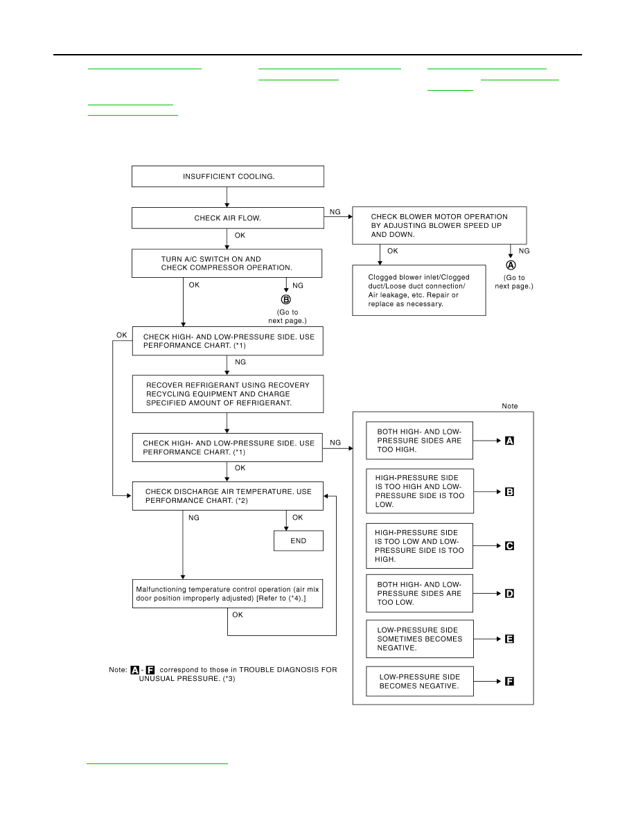
TROUBLE DIAGNOSIS
PERFORMANCE TEST DIAGNOSIS
*10
*11
ATC-4, "Precaution for Working with
HFC-134a (R-134a)"
*12
(VK45DE)
*13
(VQ35DE) or
*1
"PERFORMANCE CHART"
*2
"PERFORMANCE CHART"
*3
"TROUBLE DIAGNOSIS FOR UN-
USUAL PRESSURE"
*4
ATC-59, "Air Mix Door Motor Circuit"
SJIA1226E