Infiniti FX35 / FX45. Manual - part 117
ATC-64
< SERVICE INFORMATION >
TROUBLE DIAGNOSIS
• Intake sensor
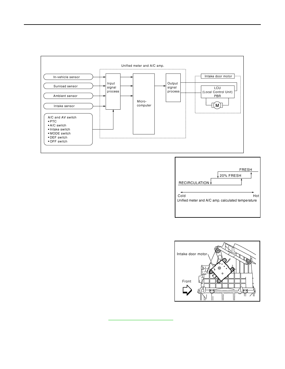
System Operation
The intake door control determines intake door position based on the ambient temperature, the intake air tem-
perature and the in-vehicle temperature. When the DEF, or OFF switches are pressed or A/C switch is OFF,
the unified meter and A/C amp. sets the intake door at the FRE position.
Intake Door Control Specification
COMPONENT DESCRIPTION
Intake Door Motor
The intake door motor is attached to the blower unit. It rotates so that
air is drawn from inlets set by the unified meter and A/C amp. Motor
rotation is conveyed to a lever which activates the intake door.
DIAGNOSIS PROCEDURE FOR INTAKE DOOR MOTOR
SYMPTOM: Intake door motor does not operate normally.
Perform diagnosis procedure. Refer to
Blower Motor Circuit
INFOID:0000000001328189
SYMPTOM: Blower motor operation is malfunctioning.
INSPECTION FLOW
SJIA1588E
RJIA1787E
RJIA0897E