Infiniti FX35 / FX45. Manual - part 14


  Index      Infiniti     Infiniti FX35 / FX45 (S50) - service repair manual 2008 year


Search            


Content   ..  12  13  14  15   ..


Infiniti FX35 / FX45. Manual - part 14


ACS-50

< SERVICE INFORMATION >

[ICC]

TROUBLE DIAGNOSIS FOR SELF-DIAGNOSTIC ITEMS

2.

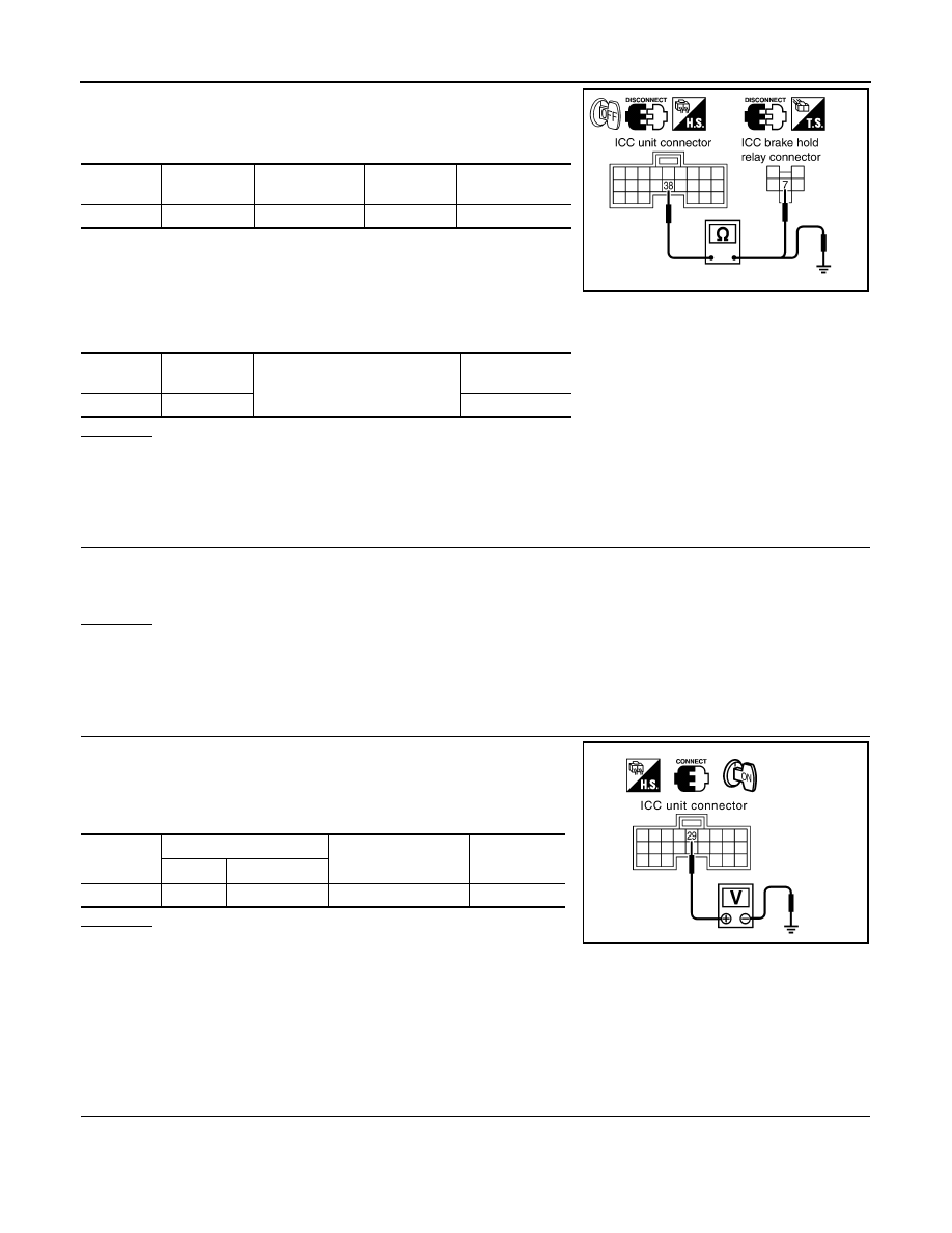
Disconnect ICC unit.

3.

Check continuity between ICC unit harness connector and ICC
brake hold relay harness connector.

4.

Check continuity between ICC unit harness connector and ground.

OK or NG

OK

>> GO TO 18.

NG

>> 1.

Repair harness between ICC unit and ICC brake hold relay.

2.

Erase DTC and perform ICC system running test. Then, perform self-diagnosis of ICC system
again.

18.

CHECK ICC BRAKE HOLD RELAY 

1.

Connect ICC unit connector and ICC brake hold relay.

2.

Disconnect stop lamp switch connector.

3.

Perform “Active Test” (“STOP LAMP”) with CONSULT-III, and make sure that stop lamp is illuminated.

OK or NG

OK

>> GO TO 19.

NG

>> 1.

Replace ICC brake hold relay.

2.

Erase DTC and perform ICC system running test. Then perform self-diagnosis of ICC system
again.

19.

CHECK ICC UNIT STANDARD VOLTAGE 

1.

Connect stop lamp switch connector.

2.

Perform “Active Test” (“STOP LAMP”: “STP LMP DRIVE ON”)
with CONSULT-III, check voltage between ICC unit harness
connector and ground.

OK or NG

OK

>> 1.

Replace ICC unit.

2.

Erase DTC and perform ICC system running test. Then perform self-diagnosis of ICC system
again.

NG

>> 1.

Replace stop lamp switch.

2.

Erase DTC and perform ICC system running test. Then perform self-diagnosis of ICC system
again.

DTC 92 ECM CIRCUIT

INFOID:0000000001328839

1.

PERFORM SELF-DIAGNOSIS OF ICC SYSTEM

1.

Perform self-diagnosis of ICC system.

2.

Check if “DTC 20 CAN COMM CIRCUIT” other than “DTC 92 ECM CIRCUIT” is indicated in self-diagnosis
item in the display.

ICC unit 

connector

Terminal

ICC brake hold 

relay connector

Terminal

Continuity

M89

38

E14

7

Yes

SKIA6663E

ICC unit 

connector

Terminal

Ground

Continuity

M89

38

No

ICC unit 

connector

Terminal

Condition

Voltage (Ap-

prox.)

(+)

(

)

M89

29

Ground

During “Active Test”

0 V 

SKIA1200E

TROUBLE DIAGNOSIS FOR SELF-DIAGNOSTIC ITEMS

ACS-51

< SERVICE INFORMATION >

[ICC]

C

D

E

F

G

H

I

J

L

M

A

B

ACS

N

O

P

Is it indicated?

YES

>> 1.

Repair or replace applicable item.

2.

Erase DTC and perform ICC system running test. Then perform self-diagnosis of ICC system
again.

NO

>> GO TO 2.

2.

PERFORM SELF-DIAGNOSIS OF ECM

1.

Perform self-diagnosis of ECM.

2.

Check if malfunction is indicated.

Is malfunction indicated?

YES

>> 1.

Repair or replace applicable item.

2.

Erase DTC and perform ICC system running test. Then perform self-diagnosis of ICC system
again.

NO

>> 1.

Replace ICC unit.

2.

Erase DTC and perform ICC system running test. Then perform self-diagnosis of ICC system
again.

DTC 96 NP RANGE

INFOID:0000000001328840

1.

CHECK CONNECTOR ICC UNIT

1.

Turn ignition switch OFF.

2.

Disconnect ICC unit connector, and connect them securely again.

3.

Erase DTC and then perform ICC system running test. Then perform self-diagnosis of ICC system again.

Is malfunction indicated?

YES

>> GO TO 2.

NO

>>

Poor connector connection

1.

Check connector. (Check connector housing for disconnected, loose, bent, and collapsed ter-
minals. If any malfunction is detected, repair applicable part.)

2.

Erase DTC and perform ICC system running test. Then perform self-diagnosis of ICC system
again.

2.

CHECK NP RANGE SWITCH SIGNAL 

With “Data Monitor” of “ICC”, check that “NP RANGE SW” operates normally.

OK or NG

OK

>> GO TO 5.

NG

>> GO TO 3.

3.

CHECK HARNESS BETWEEN ICC UNIT AND TCM

1.

Turn ignition switch OFF.

2.

Disconnect ICC unit connector and A/T assembly connector.

3.

Check continuity between ICC unit harness connector and A/T
assembly harness connector.

4.

Check continuity between ICC unit harness connector and ground.

OK or NG

OK

>> GO TO 4.

ICC unit 

connector

Terminal

A/T assembly 

connector

Terminal

Continuity

M88

7

F44

9

Yes

PKIB1447E

ICC unit 

connector

Terminal

Ground

Continuity

M88

7

No

ACS-52

< SERVICE INFORMATION >

[ICC]

TROUBLE DIAGNOSIS FOR SELF-DIAGNOSTIC ITEMS

NG

>> 1.

Repair harness between ICC unit and A/T assembly.

2.

Erase DTC and perform ICC system running test. Then perform self-diagnosis of ICC system
again.

4.

CHECK TCM START SIGNAL CIRCUIT

Check TCM start signal. Refer to 

AT-99, "Diagnosis Procedure"

.

OK or NG

OK

>> 1.

Replace ICC unit.

2.

Erase DTC and perform ICC system running test. Then perform self-diagnosis of ICC system
again.

NG

>> 1.

Repair or replace damaged parts.

2.

Erase DTC and perform ICC system running test. Then perform self-diagnosis of ICC system
again.

5.

CHECK SHIFT POSITION SIGNAL

With TCM diagnosis, check that shift operates normally. Refer to 

AT-103, "Diagnosis Procedure"

.

OK or NG

OK

>> 1.

Replace ICC unit.

2.

Erase DTC and perform ICC system running test. Then perform self-diagnosis of ICC system
again.

NG

>> 1.

Perform TCM self-diagnosis.

2.

After repairing or replacing applicable item, erase DTC and perform ICC system running test.
Then perform self-diagnosis of ICC system again.

DTC 97 AT CIRCUIT

INFOID:0000000001328841

1.

CHECK AT CIRCUIT

With TCM diagnosis, check that shift operates normally. Refer to 

AT-103, "Diagnosis Procedure"

.

OK or NG

OK

>> 1.

Replace ICC unit.

2.

Erase DTC and perform ICC system running test. Then perform self-diagnosis of ICC system
again.

NG

>> 1.

Perform TCM self-diagnosis.

2.

After repairing or replacing applicable item, erase DTC and perform ICC system running test.
Then perform self-diagnosis of ICC system again.

DTC 98 GEAR POSITION

INFOID:0000000001328842

1.

PERFORM SELF-DIAGNOSIS OF ICC SYSTEM

1.

Perform self-diagnosis of ICC system.

2.

Check if “DTC 43 ABS/TCS/VDC CIRC” or “DTC 41 VHCL SPEED SE CIRC” other than “DTC 98 GEAR
POSITION” is indicated in self-diagnosis item in the display.

Is any indicated?

YES

>> 1.

Repair or replace applicable item.

2.

Erase DTC and perform ICC system running test. Then perform self-diagnosis of ICC system
again.

NO

>> GO TO 2.

2.

CHECK VEHICLE SPEED SIGNAL

With “Data Monitor” of “ICC”, check that “VHCL SPEED SE” is normal.

OK or NG

OK

>> GO TO 3.

NG

>> 1.

Replace ICC unit.

2.

Erase DTC and perform ICC system running test. Then perform self-diagnosis of ICC system
again.

3.

CHECK SHIFT GEAR POSITION 

Check that gear positions are correct in A/T.

TROUBLE DIAGNOSIS FOR SELF-DIAGNOSTIC ITEMS

ACS-53

< SERVICE INFORMATION >

[ICC]

C

D

E

F

G

H

I

J

L

M

A

B

ACS

N

O

P

OK or NG

OK

>> GO TO 5.

NG

>> GO TO 4.

4.

CHECK TCM GEAR POSITION SIGNAL 

With “Data Monitor” of “TCM”, check that gear positions are correct.
OK or NG

OK

>> 1.

Replace ICC unit.

2.

Erase DTC and perform ICC system running test. Then perform self-diagnosis of ICC system
again.

NG

>> 1.

Perform TCM self-diagnosis.

2.

After repairing or replacing applicable item, erase DTC and perform ICC system running test.
Then perform self-diagnosis of ICC system again.

5.

CHECK TCM TURBINE ROTATION 

With TCM diagnosis, check that turbine rpm is normal. Refer to 

AT-106, "Diagnosis Procedure"

.

OK or NG

OK

>> 1.

Replace ICC unit.

2.

Erase DTC and perform ICC system running test. Then perform self-diagnosis of ICC system
again.

NG

>> 1.

Perform TCM self-diagnosis.

2.

After repairing or replacing applicable item, erase DTC and perform ICC system running test.
Then perform self-diagnosis of ICC system again.

DTC 102 RADAR STAIN

INFOID:0000000001328843

1.

VISUAL INSPECTION 1

Check that there is no contamination and foreign material on ICC sensor body window.

OK or NG

OK

>> GO TO 2.

NG

>> 1.

If any, remove them.

2.

Erase DTC and perform ICC system running test. Then perform self-diagnosis of ICC system
again.

2.

VISUAL INSPECTION 2

Check ICC sensor body window for cracks.

OK or NG

OK

>> GO TO 3.

NG

>> 1.

Replace ICC sensor, and adjust laser beam aiming.

2.

Erase DTC and perform ICC system running test. Then perform self-diagnosis of ICC system
again.

3.

ASKING COMPLAINTS 

1.

Ask if there is any trace of contamination or foreign material on ICC sensor.

2.

Ask if vehicle was driven in snow or ICC sensor was frosted.

3.

Ask if ICC sensor was fogged temporarily. (Front window glass may have also tended to be fogged.)

Is there any symptom?

YES

>> Explain difference in displays between contamination detection result and current indication to

customer, and tell them “This is not malfunction”.

NO

>> 1.

Replace ICC sensor, and adjust laser beam aiming.

2.

Erase DTC and perform ICC system running test. Then perform self-diagnosis of ICC system
again.

DTC 103 LASER SENSOR FAIL

INFOID:0000000001328844

1.

PERFORM SELF-DIAGNOSIS OF ICC SYSTEM

1.

Perform self-diagnosis of ICC system.


Content   ..  12  13  14  15   ..