Infiniti FX35, FX50 (S51). Manual - part 990


  Index      Infiniti     Infiniti FX35, FX50 (S51) - service repair manual 2010 year


Search            


Content   ..  988  989  990  991   ..


Infiniti FX35, FX50 (S51). Manual - part 990


EM-260

< UNIT DISASSEMBLY AND ASSEMBLY >

[VK50VE]

CYLINDER BLOCK

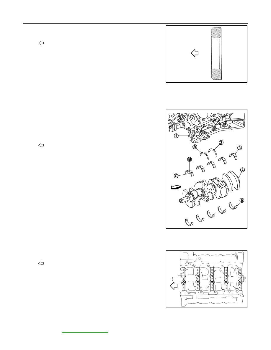
• Press-fit pilot converter with its chamfering side facing crank-

shaft as shown in the figure.

5.

Install main bearings and thrust bearings as per the following:

CAUTION:

Be careful not to drop main bearing, and to scratch the surface.

a.

Remove dust, dirt, and engine oil on bearing mating surfaces of cylinder block and main bearing caps.

b.

Install thrust bearings (2) to both sides of the No. 3 journal hous-
ing on cylinder block (1).

• Install thrust bearings with the oil groove (A) facing crankshaft

arm (outside). 

c.

Install main bearings paying attention to the direction.
• Main bearing with oil hole (B) and groove (C) goes on cylinder

block. The one without them goes on main bearing cap.

• Before installing main bearings, apply engine oil to the bearing

surface (inside). Do not apply engine oil to the back surface,
but thoroughly clean it.

• When installing, align main bearing stopper protrusion to cut-

out of cylinder block and main bearing.

• Ensure the oil holes on cylinder block and those on the corre-

sponding bearing are aligned.

6.

Install crankshaft to cylinder block.
• While turning crankshaft by hand, check that it turns smoothly. 

7.

Install main bearing caps as per the following:
• Align the identification number to the journal position to install.

• Install it with the front mark (indicated by stamping) facing the

front of engine.

• Using plastic hammer or similar tool, tap them lightly to seat

them on the installation position.
NOTE:
Main bearing cap cannot be replaced as a single parts,
because it is machined together with cylinder block.

8.

Install each main bearing cap bolts as per the following:

CAUTION:

If main bearing cap bolts and sub bolts are re-used, check their outer diameters before installa-
tion. Refer to 

EM-265, "Inspection"

.

: Crankshaft side

JPBIA0210ZZ

3

: Main bearing (upper) (cylinder block side)

4

: Crankshaft

5

: Main bearing (lower) (main bearing cap side)

: Engine front

JPBIA2148ZZ

: Engine front

JPBIA2380ZZ

CYLINDER BLOCK

EM-261

< UNIT DISASSEMBLY AND ASSEMBLY >

[VK50VE]

C

D

E

F

G

H

I

J

K

L

M

A

EM

N

P

O

a.

Apply new engine oil to threads and seat surfaces of main bearing cap bolts and sub bolts.

b.

Tighten all bolts in order of (No. 1 - 30) temporarily.

c.

Tighten main bearing cap bolts (M12) in order of No. 1 - 10.

d.

Tighten main bearing cap sub bolts (M9) in order of No. 11 - 20.

e.

Tighten main bearing cap bolts (M12) in order of No. 1 - 10
(clockwise).

CAUTION:

Use the angle wrench [SST: KV10112100 (BT8653-A)] (A) to
check tightening angle. Never make judgment by visual
inspection.

f.

Tighten main bearing cap sub bolts (M9) in order of No. 11 - 20.
(clockwise)

g.

Tighten side bolts (M10) in order of No. 21 - 30.

• After installing bolts, check that crankshaft can be rotated smoothly by hand.
• Check the crankshaft end play. Refer to 

EM-287, "Cylinder Block"

.

9.

Install rear oil seal retainer.
• Apply a continuous bead of liquid gasket with tube presser

(commercial service tool) to rear oil seal retainer as shown in
the figure.

Use Genuine RTV Silicone Sealant or an equivalent. Refer
to 

GI-16, "Recommended Chemical Products and Sealants"

.

10. Install rear oil seal on rear oil seal retainer. 

• Apply new engine oil to both oil seal lip (A) and dust seal lip

(B).

• Install it so that each seal lip is oriented as shown in the figure.

CAUTION:

Be careful not to scratch or make burrs on circumference
of oil seal.

: Engine front

: 53.9 N·m (5.5 kg-m, 40 ft-lb)

: 19.6 N·m (2.0 kg-m, 14 ft-lb)

Angle tightening: 90 degrees

Angle tightening: 90 degrees

JPBIA2146ZZ

JPBIA2149ZZ

: 49.0 N·m (5.0 kg-m, 36 ft-lb)

A

: Protrusion

b

: 4.0 - 5.6 mm (0.157 - 0.220 in)

c

φ

3.4 - 4.4 mm (0.134 - 0.173 in)

JPBIA2102ZZ

: Engine inside

: Engine outside

JPBIA0054ZZ

EM-262

< UNIT DISASSEMBLY AND ASSEMBLY >

[VK50VE]

CYLINDER BLOCK

• Press in rear oil seal (1) to the position as shown in the figure.

• Using a suitable drift [outer diameter: 101 mm (3.98 in)].
• Check the garter spring is in position and seal lips are not

inverted.

11. Install piston to connecting rod as per the following: 

• Assemble so that the front mark (A) on the piston head and

the cylinder number (D) on connecting rod are positioned as
shown in the figure.

a.

Using snap ring pliers, install new snap ring to the groove of pis-
ton rear side. 
• Insert it fully into groove to install.

b.

Install piston to connecting rod.
• Using an industrial use dryer or similar tool, heat piston until piston pin can be pushed in by hand without

excess force [approximately 60 to 70

°

C (140 to 158

°

F)]. From the front to the rear, insert piston pin into

piston and connecting rod.

c.

Install new snap ring to the groove of the piston front side. 
• Insert it fully into groove to install.
• After installing, check that connecting rod moves smoothly.

12. Using a piston ring expander (commercial service tool) (A),

install piston rings.

CAUTION:

• When installing piston rings, be careful not to damage

piston.

• Be careful not to damage piston rings by expending them

excessively.

• If there is stamped mark on ring, mount it with marked side up.

B

: Rear oil seal retainer rear end face

a

: 0 - 0.5 mm (0 - 0.020 in)

JPBIA0152ZZ

B

: Oil hole

C

: Front mark

: Engine front

JPBIA2271ZZ

JPBIA0194ZZ

Stamped mark:

Top ring (A)

: 1 N

Second ring (B)

: 2 N

JPBIA1720ZZ

CYLINDER BLOCK

EM-263

< UNIT DISASSEMBLY AND ASSEMBLY >

[VK50VE]

C

D

E

F

G

H

I

J

K

L

M

A

EM

N

P

O

• Position each ring with the gap as shown in the figure referring

to the piston front mark (D).

• Check the piston ring side clearance. Refer to 

EM-265, "Inspection"

.

13. Install connecting rod bearings to connecting rod and connecting rod bearing cap.

CAUTION:

Be careful not to drop connecting rod bearing, and to scratch the surface.
• Before installing connecting rod bearings, apply engine oil to the bearing surface (inside). Do not apply

engine oil to the back surface, but thoroughly clean it. 

• When installing, align connecting rod bearing stopper protru-

sion (B) with cutout (A) of connecting rods and connecting rod
bearing caps to install. 

• Ensure the oil hole (C) on connecting rod and that on the cor-

responding bearing are aligned. 

14. Install piston and connecting rod assembly to crankshaft. 

• Position crankshaft pin corresponding to connecting rod to be installed onto the bottom dead center. 
• Apply engine oil sufficiently to the cylinder bore, piston and crankshaft pin journal.
• Match the cylinder position with the cylinder number on connecting rod to install. 
• Be sure that front mark on piston crown is facing the front of the engine.
• Using a piston ring compressor [SST: EM03470000 (J-8037)]

(A) or suitable tool, install piston with the front mark on the pis-
ton crown facing the front of the engine.

CAUTION:

Be careful not to damage the cylinder wall and crankshaft
pin, resulting from an interference of the connecting rod big
end.

15. Install connecting rod bearing cap.

• Match the stamped cylinder number marks on connecting rod

with those on connecting rod bearing cap to install.

a

: 90 degrees

b

: 45 degrees

C

: Top ring gap

E

: Oil ring upper or lower rail gap (either of them)

F

: Second ring and oil ring spacer gap

JPBIA0205ZZ

JPBIA2272ZZ

PBIC3244J

A

:  Sample  codes

B

: Bearing stopper groove

C

: Small-end diameter grade

D

: Big-end diameter grade

E

: Weight grade

F

: Cylinder No.

G

: Management code

JPBIA2273ZZ


Content   ..  988  989  990  991   ..