Infiniti FX35, FX50 (S51). Manual - part 956
EM-124
< UNIT DISASSEMBLY AND ASSEMBLY >
[VQ35HR]
CYLINDER BLOCK
• Check the piston ring side clearance. Refer to
.
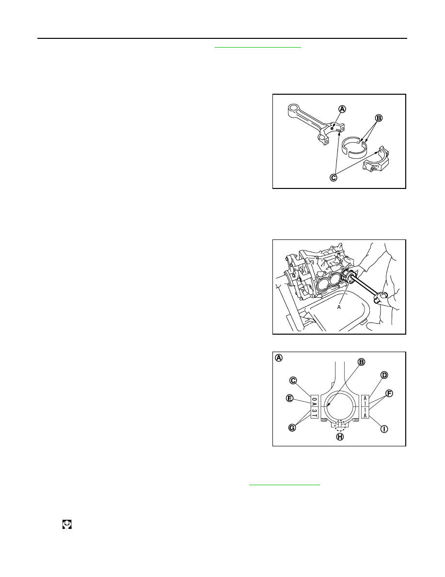
11. Install connecting rod bearings to connecting rod and connecting rod bearing cap.
CAUTION:
Be careful not to drop connecting rod bearing, and to scratch the surface.
• Before installing connecting rod bearings, apply engine oil to the bearing surface (inside). Do not apply
engine oil to the back surface, but thoroughly clean it.
• When installing, align connecting rod bearing stopper protru-
sion (B) with cutout (C) of connecting rods and connecting rod
bearing caps to install.
• Ensure the oil hole (A) on connecting rod and that on the cor-
responding bearing are aligned.
12. Install piston and connecting rod assembly to crankshaft.
• Position crankshaft pin corresponding to connecting rod to be installed onto the bottom dead center.
• Apply engine oil sufficiently to the cylinder bore, piston and crankshaft pin journal.
• Match the cylinder position with the cylinder number on connecting rod to install.
• Be sure that front mark on piston crown is facing front of engine.
• Using a piston ring compressor [SST: EM03470000 (J-8037)]
(A) or suitable tool, install piston with the front mark on the pis-
ton crown facing the front of the engine.
CAUTION:
Be careful not to damage the cylinder wall and crankshaft
pin, resulting from an interference of the connecting rod big
end.
13. Install connecting rod bearing cap.
• Match the stamped cylinder number marks on connecting rod
with those on connecting rod bearing cap to install.
• Be sure that front mark (H) on connecting rod bearing cap is facing front of the engine.
14. Tighten connecting rod bolt as per the following:
a.
Inspect the outer diameter of connecting rod bolt. Refer to
.
b.
Apply engine oil to the threads and seats of connecting rod bolts.
c.
Tighten connecting rod bolts.
d.
Completely loosen connecting rod bolts.
JPBIA0206ZZ
JPBIA0207ZZ
A
: Sample codes
B
: Bearing stopper groove
C
: Small-end diameter grade
D
: Big-end diameter grade
E
: Weight grade
F
: Cylinder No.
G
: Management code
I
: Management code
: 28.4 N·m (2.9 kg-m, 21 ft-lb)
JPBIA0208ZZ