Infiniti FX35, FX50 (S51). Manual - part 938


  Index      Infiniti     Infiniti FX35, FX50 (S51) - service repair manual 2010 year


Search            


Content   ..  936  937  938  939   ..


Infiniti FX35, FX50 (S51). Manual - part 938


EM-52

< REMOVAL AND INSTALLATION >

[VQ35HR]

IGNITION COIL, SPARK PLUG AND ROCKER COVER
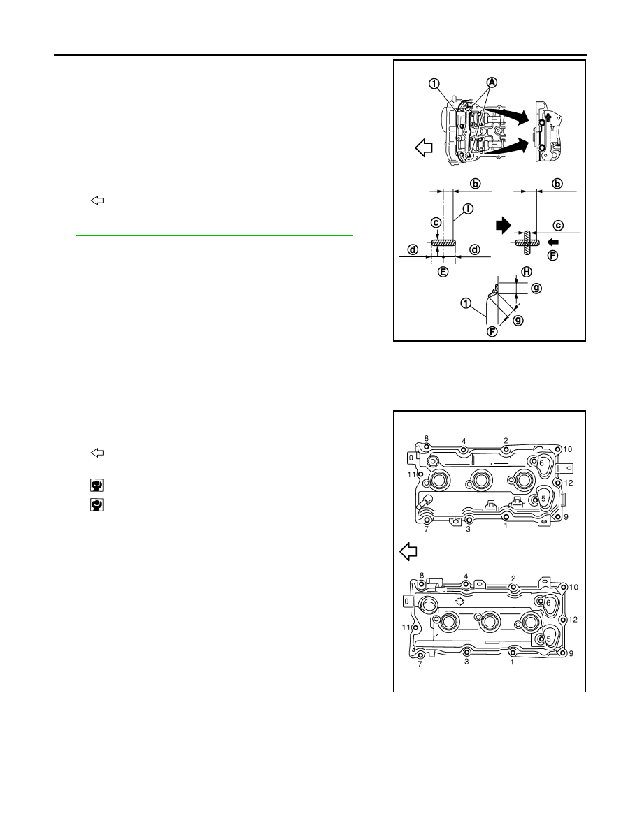
1.

Apply liquid gasket to the position shown in the figure with the
following procedure:

Use Genuine RTV silicone sealant or an equivalent. Refer to

GI-16, "Recommended Chemical Products and Sealants"

.

a.

Refer to figure (E) to apply liquid gasket to joint part of camshaft
bracket (No. 1) (1) and cylinder head.

b.

Refer to figure (H) to apply liquid gasket in 90 degrees to figure.

2.

Install rocker cover gasket to rocker cover.

3.

Install rocker cover.
• Check if rocker cover gasket is not dropped from the installation groove of rocker cover. 

4.

Tighten bolts in two steps separately in numerical order as
shown in the figure.

5.

Install in the reverse order of removal after this step. 

A

: Liquid gasket application point

F

:  View  F

I

: End surface of camshaft bracket (No. 1)

b

: 4 mm (0.16 in)

c

φ

2.5 - 3.5 mm (0.098 - 0.138 in)

d

: 5 mm (0.20 in)

g

: 10 mm (0.39 in)

: Engine front

JPBIA0274ZZ

: Engine front

 1st step

: 2.0 N·m (0.2 kg-m, 18 in-lb)

 2nd step

: 8.3 N·m (0.85 kg-m, 73 in-lb)

JPBIA0040ZZ

TIMING CHAIN

EM-53

< REMOVAL AND INSTALLATION >

[VQ35HR]

C

D

E

F

G

H

I

J

K

L

M

A

EM

N

P

O

TIMING CHAIN

Exploded View

INFOID:0000000005245146

1.

Timing chain (secondary)

2.

Camshaft sprocket (EXH)

3.

O-ring

4.

Timing chain (secondary)

5.

Camshaft sprocket (EXH) 

6.

Internal chain guide

7.

Timing chain (primary)

8.

Camshaft sprocket (INT)

9.

Timing chain tensioner (primary)

JPBIA2441GB

EM-54

< REMOVAL AND INSTALLATION >

[VQ35HR]

TIMING CHAIN

Removal and Installation

INFOID:0000000005245147

REMOVAL

1.

Release the fuel pressure. Refer to 

EC-566, "Inspection"

.

2.

Disconnect the battery cable from the negative terminal.

3.

Remove engine cover with power tool. Refer to 

EM-27, "Exploded View"

.

4.

Remove radiator reservoir tank. Refer to 

CO-14, "Exploded View"

.

5.

Remove air duct and air cleaner case assembly. Refer to 

EM-29, "Exploded View"

.

6.

Remove engine undercover with power tool.

7.

Drain engine coolant from radiator. Refer to 

CO-8, "Draining"

.

CAUTION:

• Perform this step when the engine is cold.
• Never spill engine coolant on drive belt.

8.

Remove radiator hose (upper and lower). Refer to 

CO-14, "Exploded View"

.

9.

Drain engine oil. Refer to 

LU-8, "Draining"

.

CAUTION:

• Perform this step when the engine is cold.
• Never spill engine oil on drive belt.

10. Remove drive belt. Refer to 

EM-15, "Exploded View"

.

11. Remove radiator cooling fan assembly. Refer to 

CO-14, "Exploded View"

.

12. Separate engine harnesses removing their brackets from front timing chain case.
13. Remove intake manifold collector. Refer to 

EM-31, "Exploded View"

.

14. Remove intake manifold. Refer to 

EM-34, "Exploded View"

.

15. Remove oil level gauge and oil level gauge guide.
16. Remove A/C compressor from bracket with piping connected, and temporarily secure it aside. Refer to

HA-38, "Exploded View"

.

17. Remove power steering oil pump from bracket with piping connected, and temporarily secure it aside.

Refer to 

ST-48, "VQ35HR : Exploded View"

.

18. Remove power steering oil pump bracket.

19. Remove idler pulley, auto tensioner and bracket.
20. Remove alternator and alternator bracket. Refer to 

CHG-29, "VQ35HR : Exploded View"

.

21. Remove water outlet (front) and water piping. Refer to 

CO-24, "Exploded View"

.

22. Remove valve timing control covers (bank 1 and bank 2) and gasket as per the following:
a.

Disconnect valve timing control harness connector.

10. Slack guide

11. Crankshaft sprocket

12.

Camshaft sprocket (INT)

13.

Valve timing control cover gasket 
(bank 1)

14. Seal ring

15.

Valve timing control cover (bank 1)

16. Oil level gauge

17. Oil level gauge guide

18.

O-ring

19.

Intake valve timing control solenoid 
valve (bank 2)

20. Valve timing control cover (bank 2) 21.

Valve timing control cover gasket (bank 2)

22. Front oil seal

23. Crankshaft pulley

24.

Crankshaft pulley bolt

25.

Intake valve timing control solenoid 
valve (bank 1)

26. Power steering oil pump bracket

27.

Idler pulley bracket

28. Alternator bracket

29. Water outlet (front)

30.

Front timing chain case

31. Rear timing chain case

32. O-ring

33.

O-ring

34. O-ring

A.

Refer to 

EM-97

B.

Refer to 

EM-54

C.

Oil filter

Refer to 

GI-4, "Components"

 for symbols in the figure.

TIMING CHAIN

EM-55

< REMOVAL AND INSTALLATION >

[VQ35HR]

C

D

E

F

G

H

I

J

K

L

M

A

EM

N

P

O

b.

Loosen mounting bolts in reverse order as shown in the figure.

CAUTION:

Shaft is internally jointed with camshaft sprocket (INT) cen-
ter hole. When removing, keep it horizontal until it is com-
pletely disconnected.

c.

Shaft is engaged with intake side camshaft sprocket center hole on inside. pull straight out so as not to tilt
until the joint is disengaged.
• The mating surface of magnet retarder (2) may be fitted with

the exhaust side camshaft sprocket via the engine oil. Open
valve timing control cover (1) carefully

• If the mating surface of magnet retarder is fitted with the cam-

shaft sprocket, open the cover within the range that the load is
not applied to the harness. And then, remove it so as to pre-
vent magnet retarder from dropping.

CAUTION:

• Be careful not to damage magnet retarder.
• When carrying valve timing control cover, face the mag-

net retarder side up to prevent the cover from falling from
magnet retarder. 

• Never remove magnet retarder from valve timing control cover. (Disassembly prohibited parts)

23. Remove rocker covers (bank 1 and bank 2). Refer to 

EM-50, "Exploded View"

.

24. Obtain No. 1 cylinder at TDC of its compression stroke as per the following:
a.

Rotate crankshaft pulley clockwise to align timing mark (grooved
line without color) with timing indicator.

b.

Check that intake and exhaust cam noses on No. 1 cylinder
(engine front side of bank 1) are located as shown in the figure.

• If not, turn crankshaft one revolution (360 degrees) and align

as shown in the figure.

25. Remove crankshaft pulley as per the following:
a.

Remove front cross bar. Refer to 

FSU-15, "Exploded View"

 (2WD models) or 

FSU-34, "Exploded View"

(AWD models)

b.

Remove power steering pipe mounting bolt. Refer to 

ST-48, "VQ35HR : Exploded View"

.

A

:  Bank  1

B

:  Bank  2

C

: Dowel pin hole

JPBIA0041ZZ

: Timing mark (grooved line without color)

JPBIA0042ZZ

JPBIA0043ZZ

: Engine front

JPBIA0044ZZ


Content   ..  936  937  938  939   ..