Infiniti FX35, FX50 (S51). Manual - part 889


  Index      Infiniti     Infiniti FX35, FX50 (S51) - service repair manual 2010 year


Search            


Content   ..  887  888  889  890   ..


Infiniti FX35, FX50 (S51). Manual - part 889


COOLING FAN

EC-1097

< DTC/CIRCUIT DIAGNOSIS >

[VK50VE]

C

D

E

F

G

H

I

J

K

L

M

A

EC

N

P

O

3.

Also check harness for short to power.

Is the inspection result normal?

YES

>> GO TO 3.

NO

>> Repair open circuit or short to power in harness or connectors.

3.

CHECK IPDM E/R GROUND CIRCUIT

1.

Disconnect IPDM E/R harness connectors E5, E6.

2.

Check the continuity between IPDM E/R harness connector and ground.

3.

Also check harness for short to power.

Is the inspection result normal?

YES

>> GO TO 4.

NO

>> Repair open circuit or short to power in harness or connectors.

4.

CHECK COOLING FAN CONTROL SIGNAL CIRCUIT

1.

Disconnect IPDM E/R harness connector E9.

2.

Check the continuity between IPDM E/R harness connector and cooling fan control module harness con-
nector.

3.

Also check harness for short to ground and short to power.

Is the inspection result normal?

YES

>> GO TO 5.

NO

>> Repair open circuit, short to ground or short to power in harness or connectors.

5.

CHECK COOLING FAN CONTROL MODULE OUTPUT SIGNAL CIRCUIT

1.

Reconnect all harness connectors disconnected.

2.

Disconnect cooling fan control module harness connectors E301, E303.

3.

Turn ignition switch ON.

4.

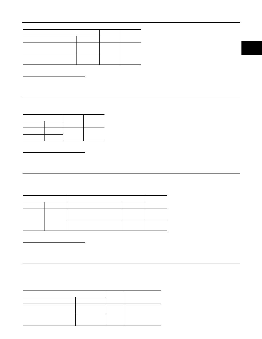
Check the voltage between cooling fan control module terminals and ground.

Cooling fan control module

Ground

Continuity

Connector

Terminal

E37

(Cooling fan control module 1)

1

Ground

Existed

E38

(Cooling fan control module 2)

1

IPDM E/R

Ground

Continuity

Connector

Terminal

E5

12

Ground

Existed

E6

41

IPDM E/R

Cooling fan control module

Continuity

Connector

Terminal

Connector

Terminal

E9

97

E37

(Cooling fan control module 1)

2

Existed

E38

(Cooling fan control module 2)

2

Existed

Cooling fan control module

Ground

Voltage

Connector

Terminal

(Cooling fan control module 1)

4

Ground

Battery voltage

(Cooling fan control module 2)

6

EC-1098

< DTC/CIRCUIT DIAGNOSIS >

[VK50VE]

COOLING FAN

Is the inspection result normal?

YES

>> GO TO 6.

NO

>> Replace malfunctioning cooling fan control module.

6.

CHECK COOLING FAN MOTORS -1 AND -2

Refer to 

EC-1099, "Component Inspection (Cooling Fan Motor)"

.

Is the inspection result normal?

YES

>> GO TO 11.

NO

>> Replace malfunctioning cooling fan motor.

7.

CHECK COOLING FAN CONTROL MODULE POWER SUPPLY CIRCUIT-II

1.

Turn ignition switch OFF.

2.

Disconnect cooling fan relay-1 and cooling fan relay-2.

3.

Check the voltage between cooling fan relay harness connector and ground.

4.

Turn ignition switch ON.

5.

Check the voltage between cooling fan relay harness connector and ground.

Is the inspection result normal?

YES

>> GO TO 9.

NO

>> GO TO 8.

8.

DETECT MALFUNCTIONING PART

Check the following.
• 10 A fuse (No. 42)
• 50 A fusible link (letter O)
• 50 A fusible link (letter S)
• IPDM E/R harness connector E7
• Harness for open or short between cooling fan relay and fuse
• Harness for open or short between cooling fan relay and battery

>> Repair open circuit, short to ground or short to power in harness or connectors.

9.

CHECK COOLING FAN CONTROL MODULE POWER SUPPLY CIRCUIT-III

1.

Turn ignition switch OFF.

2.

Disconnect IPDM E/R harness connector E6.

3.

Check the continuity between cooling fan relay harness connector and IPDM E/R harness connector.

4.

Check the continuity between cooling fan relay harness connector and cooling fan control module harness
connector.

Cooling fan relay

Ground

Voltage

Connector

Terminal

E15

(Cooling fan relay-1)

3

Ground

Battery voltage

E17

(Cooling fan relay-2)

3

Cooling fan relay

Ground

Voltage

Connector

Terminal

E15

(Cooling fan relay-1)

1

Ground

Battery voltage

Cooling fan relay

IPDM E/R

Continuity

Connector

Terminal

Connector

Terminal

E15

(Cooling fan relay-1)

2

E6

42

Existed

COOLING FAN

EC-1099

< DTC/CIRCUIT DIAGNOSIS >

[VK50VE]

C

D

E

F

G

H

I

J

K

L

M

A

EC

N

P

O

5.

Check the continuity between cooling fan relay-1 harness connector and cooling fan relay-2 harness con-
nector.

6.

Check the continuity between cooling fan relay-2 harness connector and ground.

7.

Also check harness for short to ground and short to power.

Is the inspection result normal?

YES

>> GO TO 10.

NO

>> Repair open circuit, short to ground or short to power in harness or connectors.

10.

CHECK COOLING FAN RELAYS -1 AND -2

Refer to 

EC-1100, "Component Inspection (Cooling Fan Relay)"

.

Is the inspection result normal?

YES

>> GO TO 11.

NO

>> Replace malfunctioning cooling fan relay.

11.

CHECK INTERMITTENT INCIDENT

Perfor

GI-36, "Intermittent Incident"

.

Is the inspection result normal?

YES

>> Replace IPDM E/R.

NO

>> Repair or replace harness connectors.

Component Inspection (Cooling Fan Motor)

INFOID:0000000005237602

1.

CHECK COOLING FAN MOTOR

1.

Turn ignition switch OFF.

2.

Disconnect cooling fan control module harness connectors E301, E303.

3.

Supply cooling fan control module harness connector terminals with battery voltage as per the following,
and check operation.

Is the inspection result normal?

YES

>> INSPECTION END

Cooling fan relay

Cooling fan control module

Continuity

Connector

Terminal

Connector

Terminal

E15

(Cooling fan relay-1)

5

E37

(Cooling fan control module-1)

3

Existed

E17

(Cooling fan relay-2)

5

E38

(Cooling fan control module-2)

3

Existed

Cooling fan relay

Continuity

Connector

Terminal

Connector

Terminal

E15

(Cooling fan relay-1)

5

E17

(Cooling fan relay-2)

1

Existed

Cooling fan relay

Ground

Continuity

Connector

Terminal

E17

(Cooling fan relay-1)

2

Ground

Existed

Cooling fan control module

Operation

Motor

Connector

Terminal

(+)

(–)

1

E301

4

5

Cooling fan operates.

2

E303

6

7

EC-1100

< DTC/CIRCUIT DIAGNOSIS >

[VK50VE]

COOLING FAN

NO

>> Replace malfunctioning cooling fan motor.

Component Inspection (Cooling Fan Relay)

INFOID:0000000005237603

1.

CHECK COOLING FAN RELAY

1.

Turn ignition switch OFF.

2.

Remove cooling fan relay.

3.

Check the continuity between cooling fan relay terminals under
the following conditions.

Is the inspection result normal?

YES

>> INSPECTION END

NO

>> Replace cooling fan relay.

Terminals

Conditions

Continuity

3 and 5

12 V direct current supply between terminals 1 and 2

Existed

No current supply

Not existed

MBIB0057E


Content   ..  887  888  889  890   ..