Infiniti FX35, FX50 (S51). Manual - part 876


  Index      Infiniti     Infiniti FX35, FX50 (S51) - service repair manual 2010 year


Search            


Content   ..  874  875  876  877   ..


Infiniti FX35, FX50 (S51). Manual - part 876


P1564 ICC STEERING SWITCH

EC-1045

< DTC/CIRCUIT DIAGNOSIS >

[VK50VE]

C

D

E

F

G

H

I

J

K

L

M

A

EC

N

P

O

2.

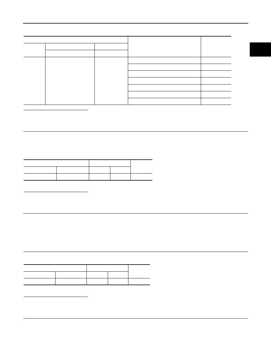
Check the voltage between ECM harness connector terminals under the following conditions.

Is the inspection result normal?

YES

>> GO TO 8.

NO

>> GO TO 3.

3.

CHECK ICC STEERING SWITCH GROUND CIRCUIT FOR OPEN AND SHORT

1.

Turn ignition switch OFF.

2.

Disconnect ECM harness connector.

3.

Disconnect combination switch harness connector.

4.

Check the continuity between combination switch and ECM harness connector.

5.

Also check harness for short to ground and short to power.

Is the inspection result normal?

YES

>> GO TO 5.

NO

>> GO TO 4.

4.

DETECT MALFUNCTIONING PART

Check the following.
• Combination switch (spiral cable)
• Harness for open and short between ECM and combination switch

>> Repair open circuit, short to ground or short to power in harness or connectors.

5.

CHECK ICC STEERING SWITCH INPUT SIGNAL CIRCUIT FOR OPEN AND SHORT

1.

Check the continuity between combination switch and ECM harness connector.

2.

Also check harness for short to ground and short to power.

Is the inspection result normal?

YES

>> GO TO 7.

NO

>> GO TO 6.

6.

DETECT MALFUNCTIONING PART

Check the following.
• Combination switch (spiral cable)
• Harness for open and short between ECM and combination switch

ECM

Condition

Voltage (V)

Connector

+

Terminal

Terminal

M160

102

(ICC steering switch signal)

111

MAIN switch: Pressed

Approx. 0

LDP switch: Pressed

Approx. 1.0

CANCEL switch: Pressed

Approx. 1.9

DISTANCE switch: Pressed

Approx. 2.6

SET/COAST switch: Pressed

Approx. 3.2

RESUME/ACCELERATE switch: Pressed

Approx. 3.7

All ICC steering switches: Released

Approx. 4.2

Combination switch

ECM

Continuity

Connector

Terminal

Connector

Terminal

16

M160

111

Existed

Combination switch

ECM

Continuity

Connector

Terminal

Connector

Terminal

13

M160

102

Existed

EC-1046

< DTC/CIRCUIT DIAGNOSIS >

[VK50VE]

P1564 ICC STEERING SWITCH

>> Repair open circuit, short to ground or short to power in harness or connectors.

7.

CHECK ICC STEERING SWITCH

Refer to 

EC-1046, "Component Inspection"

.

Is the inspection result normal?

YES

>> GO TO 8.

NO

>> Replace ICC steering switch.

8.

CHECK INTERMITTENT INCIDENT

Refer to 

GI-36, "Intermittent Incident"

.

>> INSPECTION END

Component Inspection

INFOID:0000000005237539

1.

CHECK ICC STEERING SWITCH

1.

Turn ignition switch OFF.

2.

Disconnect combination switch (spiral cable) harness connector M303.

3.

Check resistance between combination switch harness connector terminals under the following condi-
tions.

Is the inspection result normal?

YES

>> INSPECTION END

NO

>> Replace ICC steering switch

Combination switch

Condition

Resistance (

)

Connector

Terminals

M303

13 and 16

MAIN switch: Pressed

Approx. 0

LDP switch: Pressed

Approx. 270

CANCEL switch: Pressed

Approx. 620

DISTANCE switch: Pressed

Approx. 1,100

SET/COAST switch: Pressed

Approx. 1,810

RESUME/ACCELERATE switch: Pressed

Approx. 3,000

All ICC steering switches: Released

Approx. 5,420

P1568 ICC FUNCTION

EC-1047

< DTC/CIRCUIT DIAGNOSIS >

[VK50VE]

C

D

E

F

G

H

I

J

K

L

M

A

EC

N

P

O

P1568 ICC FUNCTION

DTC Logic

INFOID:0000000005237540

DTC DETECTION LOGIC

NOTE:
• If DTC P1568 is displayed with DTC UXXXX, first perform the trouble diagnosis for DTC UXXXX.
• If DTC P1568 is displayed with DTC P0605, first perform the trouble diagnosis for DTC P0605. Refer

to 

EC-962, "DTC Logic"

.

• If DTC P1568 is displayed with DTC P0607, first perform the trouble diagnosis for DTC P0607. Refer

to 

EC-964, "DTC Logic"

.

DTC CONFIRMATION PROCEDURE

1.

PRECONDITIONING

If DTC Confirmation Procedure has been previously conducted, always perform the following procedure
before conducting the next test. 
1.

Turn ignition switch OFF and wait at least 10 seconds.

2.

Turn ignition switch ON.

3.

Turn ignition switch OFF and wait at least 10 seconds.

TESTING CONDITION:
Step 2 may be conducted with the drive wheels lifted in the shop or by driving the vehicle. If a road test
is expected to be easier, it is unnecessary to lift the vehicle.

>> GO TO 2.

2.

PERFORM DTC CONFIRMATION PROCEDURE

1.

Turn ignition switch ON.

2.

Press MAIN switch on ICC steering switch.

3.

Drive the vehicle at more than 40 km/h (25 MPH).

CAUTION:

Always drive vehicle at a safe speed.

4.

Press SET/COAST switch.

5.

Check DTC.

Is DTC detected?

YES

>> Go to 

EC-1047, "Diagnosis Procedure"

.

NO

>> INSPECTION END

Diagnosis Procedure

INFOID:0000000005237541

1.

REPLACE ICC SENSOR INTEGRATED UNIT

1.

Replace ICC sensor integrated unit.

2.

Perform 

CCS-13, "ADDITIONAL SERVICE WHEN REPLACING CONTROL UNIT (ICC SENSOR INTE-

GRATED UNIT) : Special Repair Requirement"

.

3.

Check DTC of ICC sensor integrated unit. Refer to 

CCS-44, "Diagnosis Description"

.

>> INSPECTION END

DTC No.

Trouble Diagnosis Name

DTC Detecting Condition

Possible Cause

P1568

ICC function

ECM detects a difference between signals 
from ICC sensor integrated unit is out of 
specified range.

• Harness or connectors

(The CAN communication line is open or 
shorted.)

• ICC sensor integrated unit
• ECM

EC-1048

< DTC/CIRCUIT DIAGNOSIS >

[VK50VE]

P1572 ASCD BRAKE SWITCH

P1572 ASCD BRAKE SWITCH

Description

INFOID:0000000005237542

When the brake pedal is depressed, ASCD brake switch is turned OFF and stop lamp switch is turned ON.
ECM detects the state of the brake pedal by those two types of input (ON/OFF signal).
Refer to 

EC-631, "System Description"

 for the ASCD function.

DTC Logic

INFOID:0000000005237543

DTC DETECTION LOGIC

NOTE:
• If DTC P1572 is displayed with DTC P0605, first perform the trouble diagnosis for DTC P0605. Refer

to 

EC-962, "DTC Logic"

.

• This self-diagnosis has the one trip detection logic. When malfunction A is detected, DTC is not

stored in ECM memory. And in that case, 1st trip DTC and 1st trip freeze frame data are displayed.
1st trip DTC is erased when ignition switch is turned OFF. And even when malfunction A is detected
in two consecutive trips, DTC is not stored in ECM memory.

DTC CONFIRMATION PROCEDURE

1.

PRECONDITIONING

If DTC Confirmation Procedure has been previously conducted, always perform the following procedure
before conducting the next test. 
1.

Turn ignition switch OFF and wait at least 10 seconds.

2.

Turn ignition switch ON.

3.

Turn ignition switch OFF and wait at least 10 seconds.

NOTE:
The procedure for malfunction B is not described. It takes an extremely long time to complete the procedure
for malfunction B. By performing the procedure for malfunction A, the condition that causes malfunction B can
be detected.

>> GO TO 2.

2.

PERFORM DTC CONFIRMATION PROCEDURE FOR MALFUNCTION A

1.

Start engine (VDC switch OFF).

2.

Press MAIN switch and check that CRUISE indicator is displayed in combination meter.

3.

Drive the vehicle for at least 5 consecutive seconds under the following conditions.

CAUTION:

Always drive vehicle at a safe speed.
NOTE:
This procedure may be conducted with the drive wheels lifted in the shop or by driving the vehicle.
If a road test is expected to be easier, it is unnecessary to lift the vehicle.

4.

Check 1st trip DTC.

DTC No.

Trouble diagnosis name

DTC detecting condition

Possible cause

P1572

ASCD brake switch

A)

When the vehicle speed is above 30 km/h 
(19 MPH), ON signals from the stop lamp 
switch and the ASCD brake switch are 
sent to the ECM at the same time.

• Harness or connectors

(The stop lamp switch circuit is shorted.)

• Harness or connectors

(The ASCD brake switch circuit is short-
ed.)

• Stop lamp switch
• ASCD brake switch
• Incorrect stop lamp switch installation
• Incorrect ASCD brake switch installation
• ECM

B)

ASCD brake switch signal is not sent to 
ECM for extremely long time while the ve-
hicle is being driven.

Vehicle speed

More than 30 km/h (19 mph)

Selector lever

Suitable position 


Content   ..  874  875  876  877   ..