Infiniti FX35, FX50 (S51). Manual - part 810


  Index      Infiniti     Infiniti FX35, FX50 (S51) - service repair manual 2010 year


Search            


Content   ..  808  809  810  811   ..


Infiniti FX35, FX50 (S51). Manual - part 810


P0106 MANIFOLD ABSOLUTE PRESSURE SENSOR

EC-781

< DTC/CIRCUIT DIAGNOSIS >

[VK50VE]

C

D

E

F

G

H

I

J

K

L

M

A

EC

N

P

O

6.

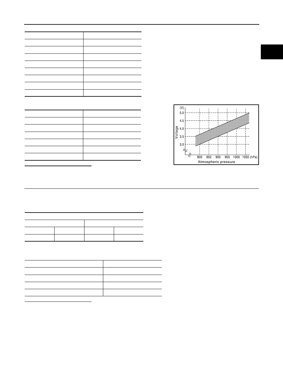
Check the manifold absolute pressure sensor value corresponding to the atmospheric pressure.

Is the inspection result normal?

YES

>> GO TO 2.

NO

>> Replace MAP sensor.

2.

CHECK MAP SENSOR-II

1.

Start engine and let it idle.

2.

Check intake manifold vacuum.

3.

Check the voltage between ECM harness connector terminals as per the following.

4.

Confirm the difference of the voltage when engine is stopped and at idling is within the values shown in
the following chart.

Is the inspection result normal?

YES

>> INSPECTION END

NO

>> Replace MAP sensor.

Altitude (m)

Compensated pressure (hPa)

0

0

200

-24

400

-47

600

-70

800

-92

1000

-114

1500

-168

2000

-218

Atmospheric pressure (hPa)

Voltage (V)

800

3.1 – 3.7

850

3.3 – 3.9

900

3.5 – 4.1

950

3.8 – 4.3

1000

4.0 – 4.6

1050

4.2 – 4.8

JMBIA0870GB

ECM

+

Connector

Terminal

Connector

Terminal

F111

69

F111

70

Intake manifold vacuum [kPA (mmHg)]

Voltage difference (V)

-40 (-300)

1.5 – 2.0

-53.3 (-400)

2.0 – 2.6

-66.7 (-500)

2.6 – 3.2

-80 (-600)

3.2 – 3.8

EC-782

< DTC/CIRCUIT DIAGNOSIS >

[VK50VE]

P010A MANIFOLD ABSOLUTE PRESSURE SENSOR

P010A MANIFOLD ABSOLUTE PRESSURE SENSOR

Description

INFOID:0000000005597971

The manifold absolute pressure (MAP) sensor is placed at intake
manifold collector. It detects intake manifold pressure and sends the
voltage signal to the ECM.
The sensor uses a silicon diaphragm which is sensitive to the
change in pressure. As the pressure increases, the voltage rises.

DTC Logic

INFOID:0000000005597979

DTC DETECTION LOGIC

NOTE:
If DTC P010A is displayed with DTC P0643, first perform the trouble diagnosis for DTC P0643. 
Refer to 

EC-965, "DTC Logic"

.

DTC CONFIRMATION PROCEDURE

1.

PRECONDITIONING 

If DTC Confirmation Procedure has been previously conducted, always perform the following procedure
before conducting the next test.
1.

Turn ignition switch OFF and wait at least 10 seconds.

2.

Turn ignition switch ON.

3.

Turn ignition switch OFF and wait at least 10 seconds.

>> GO TO 2.

2.

PERFORM DTC CONFIRMATION PROCEDURE

JMBIA0877ZZ

DTC No.

Trouble diagnosis name

DTC detecting condition

Possible cause

P010A

Manifold absolute pressure (MAP) 
sensor circuit

• An excessively low voltage from 

the sensor is sent to ECM.

• An excessively high voltage from 

the sensor is sent to ECM.

• Harness or connectors

(Battery current sensor circuit is 
open or shorted.)
(Accelerator pedal position sensor 
2 circuit is shorted.)
[Camshaft position sensor (bank 
1) circuit is shorted.]
(Crankshaft position sensor circuit 
is shorted.)
(EVAP control system pressure 
sensor circuit is shorted.)
[Exhaust valve timing control posi-
tion sensor (bank 1) circuit is short-
ed.]
(Manifold absolute pressure sen-
sor circuit is shorted.)

• Battery current sensor
• Accelerator pedal position sensor
• Camshaft position sensor (bank 1)
• Crankshaft position sensor
• EVAP control system pressure 

sensor

• Exhaust valve timing control posi-

tion sensor (bank 1)

• Manifold absolute pressure sensor

P010A MANIFOLD ABSOLUTE PRESSURE SENSOR

EC-783

< DTC/CIRCUIT DIAGNOSIS >

[VK50VE]

C

D

E

F

G

H

I

J

K

L

M

A

EC

N

P

O

1.

Start engine and let it idle for 10 seconds.

2.

Check DTC.

Is DTC detected?

YES

>> Go to 

EC-783, "Diagnosis Procedure"

.

NO

>> INSPECTION END

Diagnosis Procedure

INFOID:0000000005676464

1.

CHECK GROUND CONNECTION

1.

Turn ignition switch OFF.

2.

Check ground connection M95. Refer to Ground Inspection in 

GI-39, "Circuit Inspection"

.

Is the inspection result normal?

YES

>> GO TO 2.

NO

>> Repair or replace ground connection.

2.

CHECK MANIFOLD ABSOLUTE PRESSURE (MAP) SENSOR POWER SUPPLY CIRCUIT-I

1.

Disconnect manifold absolute pressure (MAP) sensor harness connector.

2.

Turn ignition switch ON.

3.

Check the voltage manifold absolute pressure (MAP) sensor harness connector and ground.

Is the inspection result normal?

YES

>> GO TO 9.

NO

>> GO TO 3.

3.

CHECK MANIFOLD ABSOLUTE PRESSURE (MAP) SENSOR POWER SUPPLY CIRCUIT-II

1.

Turn ignition switch OFF.

2.

Disconnect ECM harness connector.

3.

Check the continuity between manifold absolute pressure (MAP) sensor harness connector and ECM har-
ness connector.

Is the inspection result normal?

YES

>> GO TO 5.

NO

>> GO TO 4.

4.

DETECT MALFUNCTIONING PART

Check the following.
• Harness for open between battery current sensor and ECM

>> Repair open circuit.

5.

CHECK SENSOR POWER SUPPLY CIRCUIT

Check harness for short to power and short to ground, between the following terminals.

Manifold absolute pressure (MAP) sensor

Ground

Voltage (V)

Connector

Terminal

E65

1

Ground

Approx. 5

Manifold absolute pressure (MAP) sensor

ECM

Continuity

Connector

Terminal

Connector

Terminal

E65

1

F111

95

Existed

EC-784

< DTC/CIRCUIT DIAGNOSIS >

[VK50VE]

P010A MANIFOLD ABSOLUTE PRESSURE SENSOR

Is the inspection result normal?

YES

>> GO TO 6.

NO

>> Repair short to ground or short to power in harness or connectors.

6.

CHECK COMPONENTS

Check the following.
• Crankshaft position sensor (Refer to 

EC-876, "Component Inspection"

.)

• Camshaft position sensor (bank 1) (Refer to 

EC-881, "Component Inspection"

.)

• Exhaust valve timing control position sensor (bank 1) (Refer to 

EC-978, "Component Inspection"

.)

• EVAP control system pressure sensor (Refer to 

EC-917, "Component Inspection"

.)

• Manifold absolute pressure sensor (Refer to 

EC-785, "Component Inspection"

.)

Is the inspection result normal?

YES

>> GO TO 7.

NO

>> Replace malfunctioning component.

7.

CHECK APP SENSOR

Refer to 

EC-1081, "Component Inspection"

.

Is the inspection result normal?

YES

>> GO TO 14.

NO

>> GO TO 8.

8.

REPLACE ACCELERATOR PEDAL ASSEMBLY

1.

Replace accelerator pedal assembly.

2.

Perform 

EC-1082, "Special Repair Requirement"

.

>> INSPECTION END

9.

CHECK MANIFOLD ABSOLUTE PRESSURE (MAP) SENSOR GROUND CIRCUIT FOR OPEN AND

SHORT

1.

Turn ignition switch OFF.

2.

Disconnect ECM harness connector.

3.

Check the continuity between manifold absolute pressure (MAP) sensor harness connector and ECM har-
ness connector.

4.

Also check harness for short to ground and short to power.

Is the inspection result normal?

YES

>> GO TO 11.

NO

>> GO TO 10.

ECM

Sensor

Connector

Terminal

Name

Connector

Terminal

F111

87

Crankshaft position sensor

F2

1

91

Camshaft position sensor (bank 1)

F84

1

EVT control position sensor (bank 1)

F59

1

95

Battery current sensor

E21

1

EVAP control system pressure sensor

B252

3

Manifold absolute pressure sensor

F65

1

M160

99

APP sensor (Without ICC)

E112

6

APP sensor (with ICC)

E116

3

Manifold absolute pressure (MAP) sensor

ECM

Continuity

Connector

Terminal

Connector

Terminal

F65

3

F111

70

Existed


Content   ..  808  809  810  811   ..