Infiniti FX35, FX50 (S51). Manual - part 731
COOLING FAN
EC-465
< DTC/CIRCUIT DIAGNOSIS >
[VQ35HR]
C
D
E
F
G
H
I
J
K
L
M
A
EC
N
P
O
3.
CHECK IPDM E/R GROUND CIRCUIT
1.
Disconnect IPDM E/R harness connectors E5, E6.
2.
Check the continuity between IPDM E/R harness connector and ground.
3.
Also check harness for short to power.
Is the inspection result normal?
YES
>> GO TO 4.
NO
>> Repair open circuit or short to power in harness or connectors.
4.
CHECK COOLING FAN CONTROL SIGNAL CIRCUIT
1.
Disconnect IPDM E/R harness connector E9.
2.
Check the continuity between IPDM E/R harness connector and cooling fan control module 1 harness
connector.
3.
Also check harness for short to ground and short to power.
Is the inspection result normal?
YES
>> GO TO 5.
NO
>> Repair open circuit, short to ground or short to power in harness or connectors.
5.
CHECK COOLING FAN CONTROL MODULE 1 OUTPUT SIGNAL CIRCUIT
1.
Reconnect all harness connectors disconnected.
2.
Disconnect cooling fan control module 1 harness connectors E301, E302.
3.
Turn ignition switch ON.
4.
Check the voltage between cooling fan control module 1 terminals and ground.
Is the inspection result normal?
YES
>> GO TO 6.
NO
>> Replace cooling fan control module 1.
6.
CHECK COOLING FAN MOTORS -1 AND -2
EC-466, "Component Inspection (Cooling Fan Motor)"
Is the inspection result normal?
YES
>> GO TO 11.
NO
>> Replace malfunctioning cooling fan motor.
7.
CHECK COOLING FAN CONTROL MODULE 1 POWER SUPPLY CIRCUIT-II
1.
Turn ignition switch OFF.
2.
Disconnect cooling fan relay 1.
3.
Turn ignition switch ON.
4.
Check the voltage between cooling fan relay 1 harness connector and ground.
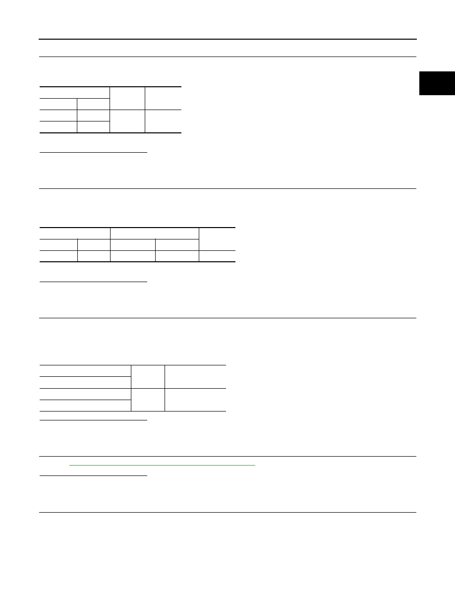
IPDM E/R
Ground
Continuity
Connector
Terminal
E5
12
Ground
Existed
E6
41
IPDM E/R
Cooling fan control module 1
Continuity
Connector
Terminal
Connector
Terminal
E9
97
E37
2
Existed
Cooling fan control module 1
Ground
Voltage
Terminal
4
Ground
Battery voltage
6