Infiniti FX35, FX50 (S51). Manual - part 625


  Index      Infiniti     Infiniti FX35, FX50 (S51) - service repair manual 2010 year


Search            


Content   ..  623  624  625  626   ..


Infiniti FX35, FX50 (S51). Manual - part 625


MULTIPORT FUEL INJECTION SYSTEM

EC-41

< SYSTEM DESCRIPTION >

[VQ35HR]

C

D

E

F

G

H

I

J

K

L

M

A

EC

N

P

O

Accordingly, the difference between the basic and theoretical mixture ratios is monitored in this system. This is
then computed in terms of “injection pulse duration” to automatically compensate for the difference between
the two ratios.
“Fuel trim” refers to the feedback compensation value compared against the basic injection duration. Fuel trim
includes short-term fuel trim and long-term fuel trim.
“Short term fuel trim” is the short-term fuel compensation used to maintain the mixture ratio at its theoretical
value. The signal from A/F sensor 1 indicates whether the mixture ratio is RICH or LEAN compared to the the-
oretical value. The signal then triggers a reduction in fuel volume if the mixture ratio is rich, and an increase in
fuel volume if it is lean.
“Long-term fuel trim” is overall fuel compensation carried out over time to compensate for continual deviation
of the short-term fuel trim from the central value. Continual deviation will occur due to individual engine differ-
ences, wear over time and changes in the usage environment.

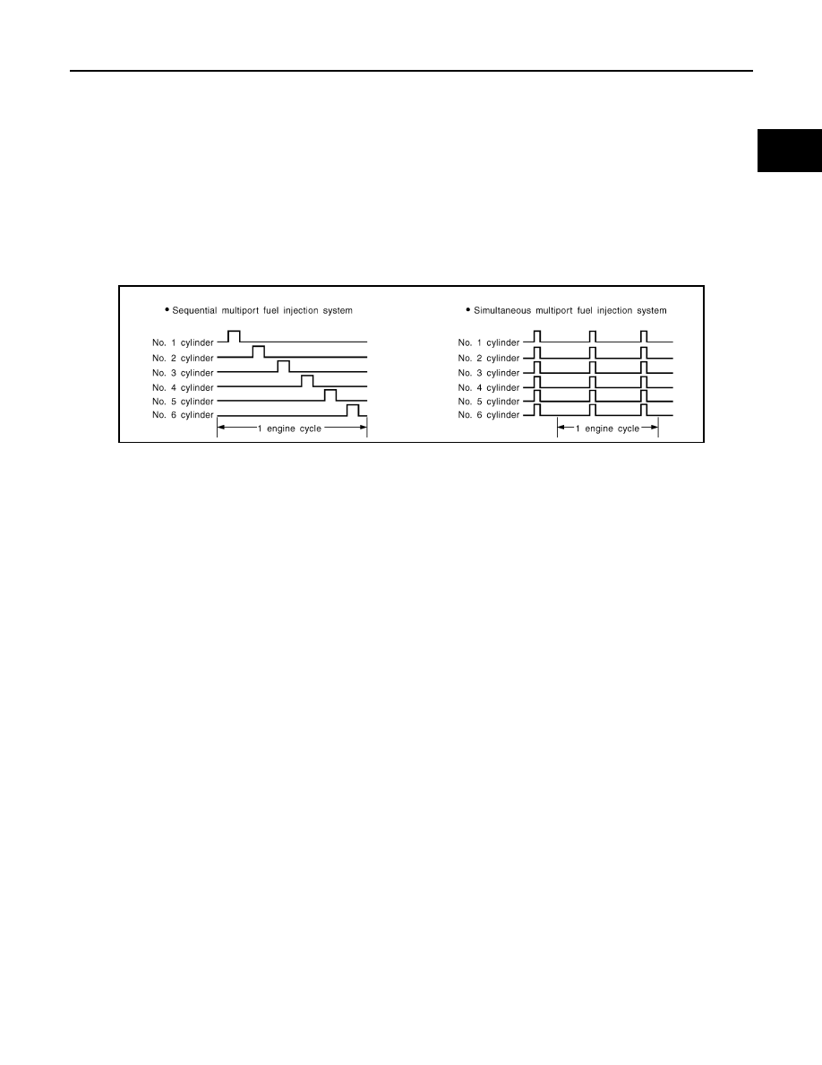
FUEL INJECTION TIMING

Two types of systems are used.
• Sequential Multiport Fuel Injection System

Fuel is injected into each cylinder during each engine cycle according to the firing order. This system is used
when the engine is running.

• Simultaneous Multiport Fuel Injection System

Fuel is injected simultaneously into all six cylinders twice each engine cycle. In other words, pulse signals of
the same width are simultaneously transmitted from the ECM.
The six injectors will then receive the signals 2 times for each engine cycle.
This system is used when the engine is being started and/or if the fail-safe system (CPU) is operating.

FUEL SHUT-OFF

Fuel to each cylinder is cut off during deceleration, operation of the engine at excessively high speeds or oper-
ation of the vehicle at excessively high speeds.

SEF179U

EC-42

< SYSTEM DESCRIPTION >

[VQ35HR]

MULTIPORT FUEL INJECTION SYSTEM

Component Parts Location

INFOID:0000000005568460

1.

IPDM E/R

2.

Battery current sensor

3.

Cooling fan relay

4.

Mass air flow sensor (with intake air 
temperature sensor) (bank 1)

5.

Refrigerant pressure sensor

6.

Cooling fan motor-2

7.

Intake valve timing control solenoid 
valve

8.

Exhaust valve timing control magnet 
retarder

9.

Cooling fan control module

10. Cooling fan motor-1

11.

Mass air flow sensor (with intake air 
temperature sensor) (bank 2)

12. ICC brake hold relay (ICC models)

13. Ignition coil (with power transistor) 

and spark plug (bank 2)

14. Electric throttle control actuator 

(bank 2)

15. A/F sensor 1 (bank 2)

16. Fuel injector (bank 2)

17. Camshaft position sensor

18. Engine coolant temperature sensor

19. Knock sensor

20. Exhaust valve timing control position 

sensor

21. EVAP canister purge volume control 

solenoid valve

22. Fuel injector (bank 1)

23. Ignition coil (with power transistor) 

and spark plug (bank 1)

24. EVAP service port

25. A/F sensor 1 (bank 1)

26. Crankshaft position sensor

27. Electric throttle control actuator 

(bank 1)

JMBIA1496ZZ

MULTIPORT FUEL INJECTION SYSTEM

EC-43

< SYSTEM DESCRIPTION >

[VQ35HR]

C

D

E

F

G

H

I

J

K

L

M

A

EC

N

P

O

1.

Mass air flow sensor (with intake air 
temperature sensor) (bank 1)

2.

Mass air flow sensor (with intake air 
temperature sensor) (bank 2)

1.

Electric throttle control actuator 
(bank 1)

2.

Electric throttle control actuator 
(bank 2)

1.

Cooling fan control module

2.

Cooling fan motor-1

3.

Cooling fan motor-2

4.

Cooling fan relay

JMBIA1497ZZ

JMBIA0004ZZ

JMBIA1498ZZ

EC-44

< SYSTEM DESCRIPTION >

[VQ35HR]

MULTIPORT FUEL INJECTION SYSTEM

JMBIA1683GB

1.

A/F sensor 1 (bank 2)

2.

Heated oxygen sensor 2 (bank 2)

3.

Heated oxygen sensor 2 (bank 2) 
harness connector

4.

Heated oxygen sensor 2 (bank 1) 
harness connector

5.

Heated oxygen sensor 2 (bank 1)

6.

A/F sensor 1 (bank 1)

: Vehicle front

1.

A/F sensor 1 (bank 1) harness con-
nector

2.

A/F sensor 1 (bank 2) harness con-
nector

: Vehicle front

JMBIA1499ZZ

JMBIA0006ZZ


Content   ..  623  624  625  626   ..