Infiniti FX35, FX50 (S51). Manual - part 597


  Index      Infiniti     Infiniti FX35, FX50 (S51) - service repair manual 2010 year


Search            


Content   ..  595  596  597  598   ..


Infiniti FX35, FX50 (S51). Manual - part 597


DIFFERENTIAL ASSEMBLY

DLN-223

< UNIT DISASSEMBLY AND ASSEMBLY >

[REAR FINAL DRIVE: R200]

C

E

F

G

H

I

J

K

L

M

A

B

DLN

N

O

P

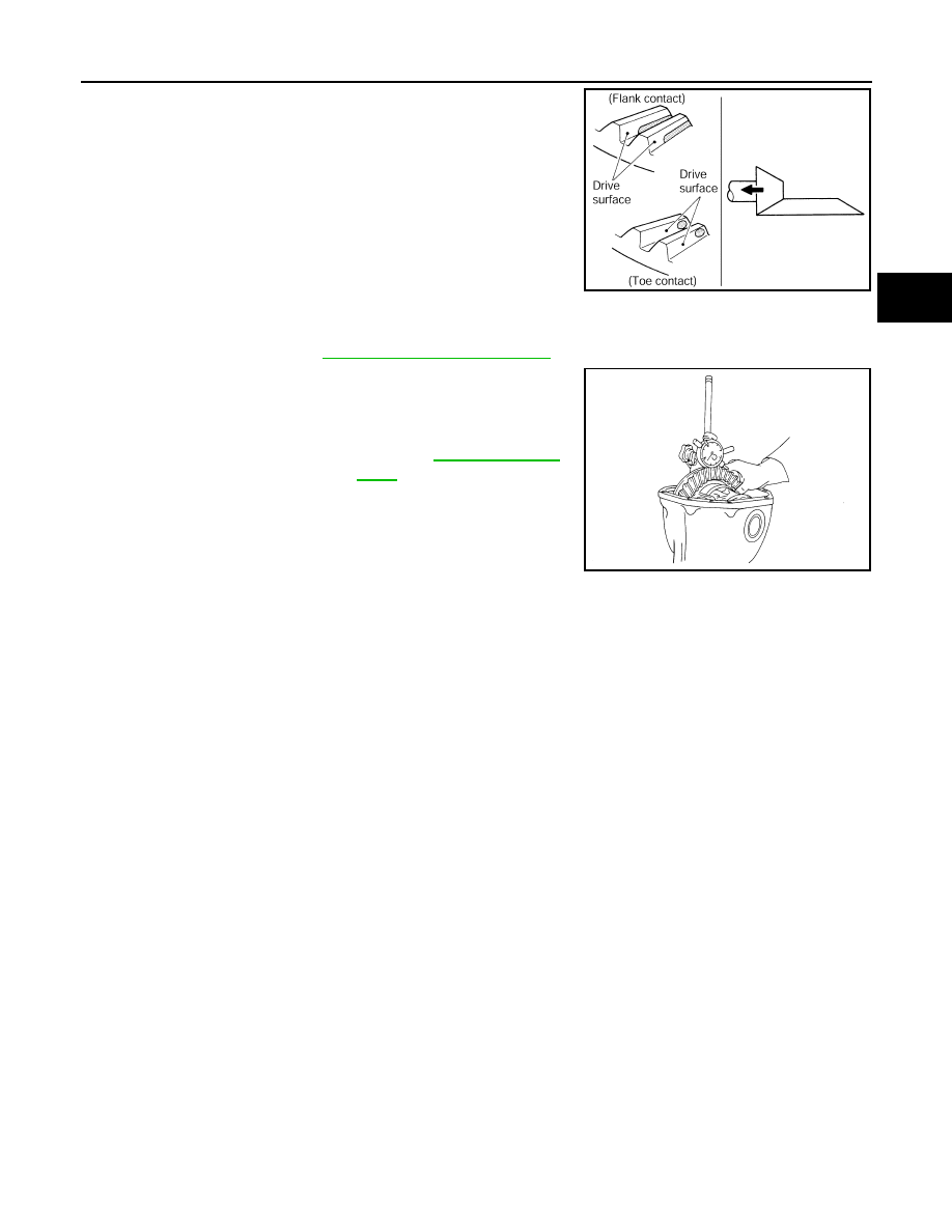
• If the tooth contact is near the flank (flank contact), or near the

toe (toe contact), thin pinion height adjusting washers to move
drive pinion farther from drive gear.

BACKLASH

Before inspection and adjustment, drain gear oil.

1.

Remove rear cover. Refer to 

DLN-212, "2WD : Disassembly"

.

2.

Fit a dial indicator to the drive gear face to measure the back-
lash.

• If the backlash is outside of the specified value, change the

thickness of side bearing adjusting washer.

CAUTION:

Never change the total amount of washers as it changes the bearing preload.

2WD : Inspection After Disassembly

INFOID:0000000005249241

DRIVE GEAR AND DRIVE PINION

• Clean up the disassembled parts.
• If the gear teeth never mesh or line-up correctly, determine the cause and adjust or replace as necessary.
• If the gears are worn, cracked, damaged, pitted or chipped (by friction) noticeably, replace with new drive

gear and drive pinion as a set.

BEARING

• Clean up the disassembled parts.
• If any chipped (by friction), pitted, worn, rusted or scratched marks, or unusual noise from the bearing is

observed, replace as a bearing assembly (as a new set).

SIDE GEAR AND PINION MATE GEAR

• Clean up the disassembled parts.
• If any cracks or damage on the surface of the tooth is found, replace.
• If any worn or chipped mark on the contact sides of the thrust washer is found, replace.

SIDE GEAR THRUST WASHER AND PINION MATE THRUST WASHER

• Clean up the disassembled parts.
• If it is chipped (by friction), damaged, or unusually worn, replace.

OIL SEAL

• Whenever disassembled, replace.

PDIA0441E

Standard

Backlash

: Refer to 

DLN-256, "Back-

lash"

.

When the backlash is large:

Make drive gear back side adjusting washer thicker, 
and drive gear tooth side adjusting washer thinner by 
the same amount.

When the backlash is small:

Make drive gear back side adjusting washer thinner, 
and drive gear tooth side adjusting washer thicker by 
the same amount.

SPD513

DLN-224

< UNIT DISASSEMBLY AND ASSEMBLY >

[REAR FINAL DRIVE: R200]

DIFFERENTIAL ASSEMBLY

• If wear, deterioration of adherence (sealing force lips), or damage is detected on the lips, replace them.

DIFFERENTIAL CASE

• Clean up the disassembled parts.
• If any wear or crack on the contact sides of the differential case is found, replace.

COMPANION FLANGE

• Clean up the disassembled parts.
• If any chipped mark [about 0.1 mm, (0.004 in)] or other damage on the contact sides of the lips of the com-

panion flange is found, replace.

AWD

AWD : Exploded View

INFOID:0000000005249242

1.

Drive pinion lock nut

2.

Companion flange

3.

Front oil seal

4.

Pinion front bearing

5.

Gear carrier

6.

Side oil seal

7.

Side flange

8.

Collapsible spacer

9.

Pinion rear bearing

10. Pinion height adjusting washer

11.

Drive pinion

12. Side bearing adjusting washer

13. Side bearing

14. Side gear thrust washer

15. Circular clip

16. Side gear

17. Lock pin

18. Pinion mate gear

19. Pinion mate thrust washer

20. Pinion mate shaft

21. Drive gear

22. Differential case

23. Bearing cap

24. Filler plug

25. Gasket

26. Rear cover

27. Drain plug

A.

Oil seal lip

B.

 Screw hole

C.

Comply with the assembly proce-
dure when tightening. Refer to 

DLN-

227, "AWD : Assembly"

.

JPDID0262GB

DIFFERENTIAL ASSEMBLY

DLN-225

< UNIT DISASSEMBLY AND ASSEMBLY >

[REAR FINAL DRIVE: R200]

C

E

F

G

H

I

J

K

L

M

A

B

DLN

N

O

P

AWD : Disassembly

INFOID:0000000005249243

1.

Drain gear oil, if necessary.

2.

Remove side flange.

3.

Remove rear cover mounting bolts.

4.

Remove rear cover to insert the seal cutter (A) [SST:
KV10111100 (J-37228)] between gear carrier and rear cover.

CAUTION:

• Never damage the mating surface.
• Never insert flat-bladed screwdriver, this may damage the

mating surface.

5.

Using two 45 mm (1.77 in) spacers, mount carrier on the attach-
ment (A) [SST: KV38100800 (J-25604-01)].

6.

For proper reinstallation, paint matching marks on one side of
the bearing cap.

CAUTION:

• For matching marks, use paint. Never damage bearing

caps and gear carrier.

• Bearing caps are manufactured as integral molding. Use

the matching marks to them in their original positions.

: Apply gear oil.

: Apply anti-corrosion oil.

: Apply Genuine Silicone RTV or equivalent. Refer to 

GI-16, "Recommended Chemical Products and Sealants"

.

: Apply Genuine High Strength Thread Locking Sealant or equivalent. Refer to 

GI-16, "Recommended Chemical Products 

and Sealants"

.

Refer to 

GI-4, "Components"

 for symbols not described above.

PDIA0756J

PDIA0757J

SDIA1795E

DLN-226

< UNIT DISASSEMBLY AND ASSEMBLY >

[REAR FINAL DRIVE: R200]

DIFFERENTIAL ASSEMBLY

7.

Remove bearing caps.

8.

Lift differential case assembly out with a suitable tool.

• Keep side bearing outer races together with inner race. Never

mix them up.
Also, keep side bearing adjusting washers together with bear-
ings.

9.

Remove side bearing inner race.
To prevent damage to bearing, engage puller jaws in groove
(

).

CAUTION:

• To prevent damage to the side bearing and drive gear,

place copper plates between these parts and vise.

• It is not necessary to remove side bearing inner race

except when it is replaced.

S-PD343

PDIA0547E

SPD527

A

: Puller [SST: ST33051001 (J-22888-20)]

B

: Base [SST: ST33061000 (J-8107-2)]

PDIA0758J


Content   ..  595  596  597  598   ..