Infiniti FX35, FX50 (S51). Manual - part 593
REAR FINAL DRIVE ASSEMBLY
DLN-207
< UNIT REMOVAL AND INSTALLATION >
[REAR FINAL DRIVE: R200]
C
E
F
G
H
I
J
K
L
M
A
B
DLN
N
O
P
UNIT REMOVAL AND INSTALLATION
REAR FINAL DRIVE ASSEMBLY
2WD
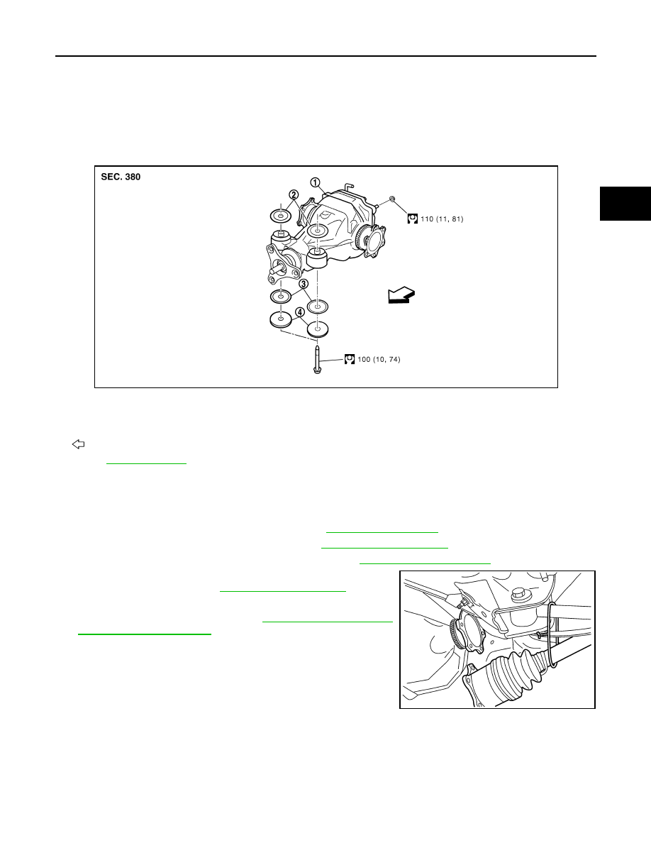
2WD : Exploded View
INFOID:0000000005249233
2WD : Removal and Installation
INFOID:0000000005249234
REMOVAL
1.
Remove center muffler with a power tool. Refer to
2.
Remove stabilizer bar with a power tool. Refer to
3.
Remove rear propeller shaft from the final drive. Refer to
4.
Remove drive shaft from final drive with a power tool. Then sus-
pend it by wire, etc. Refer to
.
5.
Remove breather hose from the final drive.
6.
Remove rear wheel sensor. Refer to
.
1.
Rear final drive assembly
2.
Upper stopper
3.
Lower stopper
4.
Washer
: Vehicle front
Refer to
JPDID0127GB
SDIA1094E