Infiniti FX35, FX50 (S51). Manual - part 590
FRONT OIL SEAL
DLN-195
< REMOVAL AND INSTALLATION >
[REAR FINAL DRIVE: R200]
C
E
F
G
H
I
J
K
L
M
A
B
DLN
N
O
P
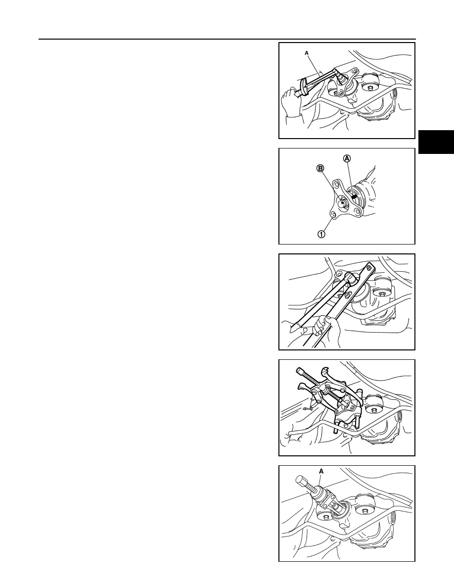
8.
Measure the total preload with the preload gauge (A) [SST:
ST3127S000 (J-25765-A)].
NOTE:
Record the preload measurement.
9.
Put matching mark (B) on the end of the drive pinion. The
matching mark (B) should be in line with the matching mark (A)
on companion flange (1).
CAUTION:
For matching mark, use paint. Never damage companion
flange and drive pinion.
NOTE:
The matching mark (A) on the final drive companion flange (1)
indicates the maximum vertical runout position.
10. Remove drive pinion lock nut using the flange wrench.
11. Remove companion flange using pullers.
12. Remove front oil seal using the puller (A) [SST: KV381054S0 (J-
34286)].
JSDIA0015ZZ
JSDIA0016ZZ
JSDIA0021ZZ
JSDIA0022ZZ
PDIA0980E