Infiniti FX35, FX50 (S51). Manual - part 561


  Index      Infiniti     Infiniti FX35, FX50 (S51) - service repair manual 2010 year


Search            


Content   ..  559  560  561  562   ..


Infiniti FX35, FX50 (S51). Manual - part 561


FRONT CASE AND REAR CASE

DLN-79

< UNIT DISASSEMBLY AND ASSEMBLY >

[TRANSFER: ETX13C]

C

E

F

G

H

I

J

K

L

M

A

B

DLN

N

O

P

VK50VE : Disassembly

INFOID:0000000005249122

1.

Remove drain plug and filler plug.

2.

Remove harness brackets.

3.

Remove main shaft oil seal from front case.

CAUTION:

Never damage the front case and main shaft.

4.

Remove front oil seal from front case.

CAUTION:

Never damage the front case and front drive shaft.

5.

Remove self-lock nut.

6.

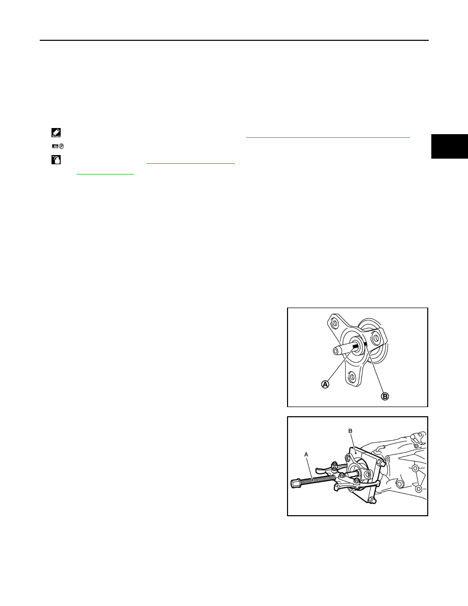
Put a matching mark (A) on main shaft. The mark should be in
line with the mark (B) on the companion flange.

CAUTION:

For the matching mark, use paint. Never damage main
shaft.

7.

Remove the companion flange with a puller and a replacer.

CAUTION:

Never damage the companion flange.

22. Oil cover

23. O-ring

24. Retainer

25. Transfer fluid temperature sensor

26. Baffle plate

27. Spacer

28. Snap ring

29. Dowel pin

30. Rear case

31. Harness bracket

32. Breather tube

33. Filler plug

34. Gasket

35. Drain plug

36. Rear bearing

37. Snap ring

38. Spacer

39. Rear oil seal

40. Companion flange

41. Self-lock nut

A.

Oil seal lip

B.

Matching surface

: Apply Genuine Anaerobic Liquid Gasket or equivalent. Refer to 

GI-16, "Recommended Chemical Products and Sealants"

.

: Apply petroleum jelly.

: Apply transfer fluid. Refer to 

MA-12, "Fluids and Lubricants"

.

Refer to 

GI-4, "Components"

 for symbols not described above.

JPDIE0104ZZ

A

: Puller (commercial service tool)

B

: Replacer (commercial service tool)

JPDIE0127ZZ

DLN-80

< UNIT DISASSEMBLY AND ASSEMBLY >

[TRANSFER: ETX13C]

FRONT CASE AND REAR CASE

8.

Remove rear oil seal from rear case with the replacer (A)
[SST:KV381054S0 (J-34286)].

CAUTION:

Never damage the rear case.

9.

Remove spacer from main shaft.

10. Remove front case and rear case fixing bolts, then remove har-

ness bracket.

*: With harness bracket.

11. Remove front case (1) from rear case by levering it up with a

suitable tool.

CAUTION:

Never damage the mating surface.

12. Remove snap ring (1) from front case.

13. Remove main shaft bearing from front case.

CAUTION:

Never use tools. Always remove by hand.

JPDIE0132ZZ

Bolts symbol

Quantity

A

14

T (TORX bolt)

1

JPDIE0108ZZ

JPDIE0140ZZ

JPDIE0109ZZ

FRONT CASE AND REAR CASE

DLN-81

< UNIT DISASSEMBLY AND ASSEMBLY >

[TRANSFER: ETX13C]

C

E

F

G

H

I

J

K

L

M

A

B

DLN

N

O

P

14. Remove snap ring (1) from main shaft.

15. Remove spacer (1) and steel ball (2) from main shaft. 

CAUTION:

Be careful not to drop the steel ball. 

16. Remove Oil pump from main shaft.
17. Remove drive chain and front drive shaft.

CAUTION:

Never use tools. Always remove by hand.

18. Remove transfer fluid temperature sensor bolt from rear case.

And then, remove transfer fluid temperature sensor (1).

19. Remove oil cover bolts from rear case. And then, remove oil

cover (1).

20. Remove retainer from AWD solenoid harness connector.

21. Remove AWD solenoid harness connector from rear case.

22. Remove O-ring from AWD solenoid harness connector.

23. Using a press, remove main shaft assembly from rear case.

JPDIE0122ZZ

JPDIE0123ZZ

JPDIE0198ZZ

JPDIE0197ZZ

JPDIE0144ZZ

DLN-82

< UNIT DISASSEMBLY AND ASSEMBLY >

[TRANSFER: ETX13C]

FRONT CASE AND REAR CASE

24. Remove snap ring (1) from rear case.

25. Remove rear bearing from rear case.

CAUTION:

Never use tools. Always remove by hand.

26. Remove baffle plate (1) from rear case.
27. Remove breather tube from rear case.

VK50VE : Assembly

INFOID:0000000005249123

1.

Install breather tube to rear case within the angle (A) shown as follows.
Install rear oil seal to rear case with the drifts within the dimen-
sion (L) shown as follows.

CAUTION:

Never reuse breather tube.

2.

Install baffle plate to rear case.

3.

Install rear bearing to rear case.

CAUTION:

Never use tools. Always install by hand.

4.

Install snap ring (1) to rear case.

CAUTION:

Never reuse snap ring.

JPDIE0111ZZ

JPDIE0112ZZ

Angle (A)

: 80 – 100

°

JPDIE0113ZZ

JPDIE0111ZZ


Content   ..  559  560  561  562   ..