Infiniti FX35, FX50 (S51). Manual - part 495
KEY SLOT ILLUMINATION
DLK-103
< DTC/CIRCUIT DIAGNOSIS >
C
D
E
F
G
H
I
J
L
M
A
B
DLK
N
O
P
KEY SLOT ILLUMINATION
Description
INFOID:0000000005239605
Blinks when Intelligent Key insertion is required.
Component Function Check
INFOID:0000000005239606
1.
CHECK FUNCTION
Check key slot illumination (“KEY SLOT ILLUMI”) Active Test mode.
Is the inspection result normal?
YES
>> Key slot function is OK.
NO
>> Refer to
DLK-103, "Diagnosis Procedure"
Diagnosis Procedure
INFOID:0000000005239607
1.
CHECK FUSE
1.
Turn ignition switch OFF.
2.
Check 10 A fuse, [No.9, located in fuse block (J/B)].
Is fuse fusing?
YES
>> Replace the blown fuse after repairing the affected circuit if a fuse is blown.
NO
>> GO TO 2.
2.
CHECK KEY SLOT ILLUMINATION OUTPUT SIGNAL
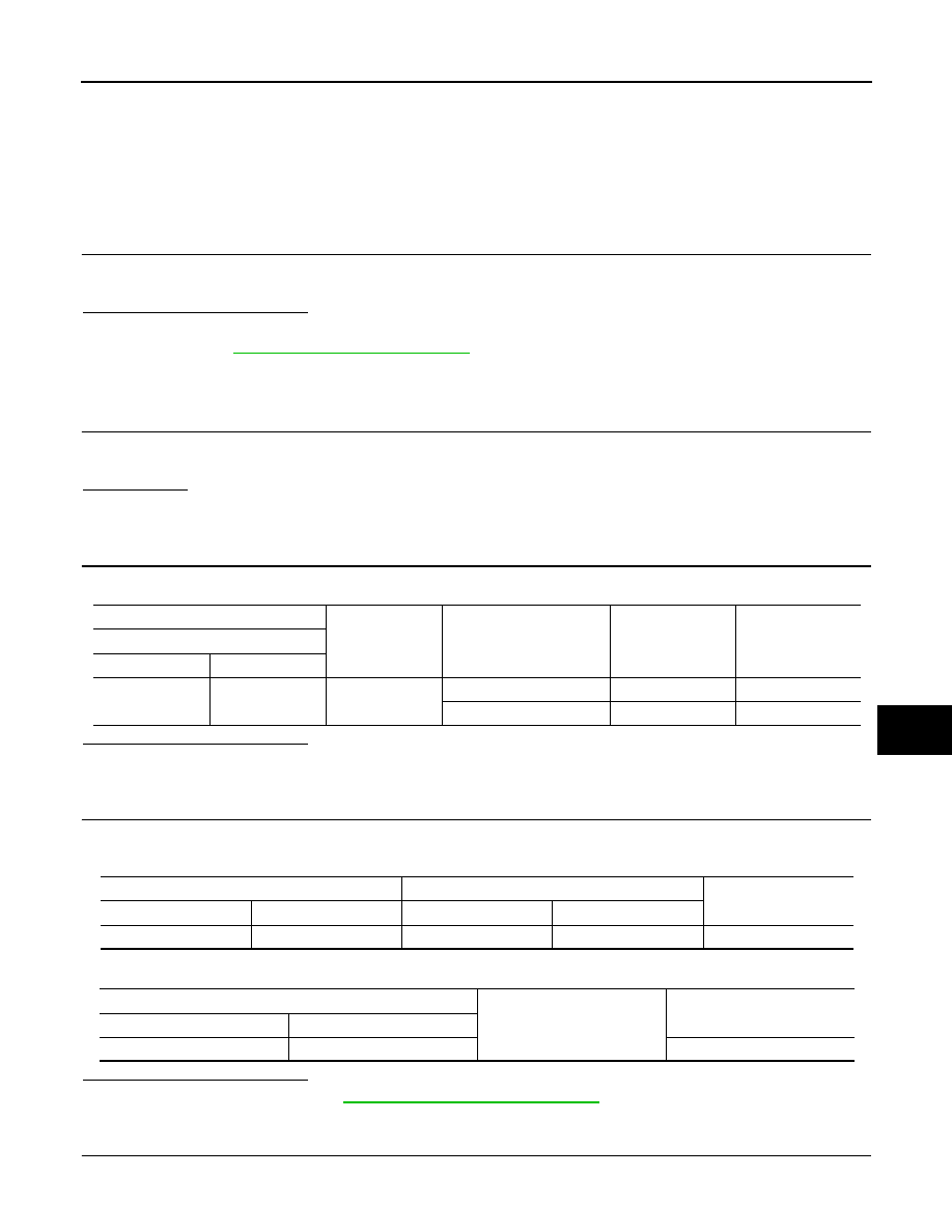
Check voltage between key slot harness connector and ground.
Is the inspection result normal?
YES
>> GO TO 3.
NO
>> GO TO 4.
3.
CHECK KEY SLOT CIRCUIT
1.
Disconnect BCM and key slot connector.
2.
Check continuity between BCM harness connector and key slot harness connector.
3.
Check continuity between BCM harness connector and ground.
Is the inspection result normal?
YES
>> Replace BCM. Refer to
BCS-83, "Removal and Installation"
NO
>> Repair or replace harness.
4.
CHECK KEY SLOT POWER SUPPLY CIRCUIT
1.
Disconnect key slot connector.
(+)
(–)
Condition
Key slot
illumination
Voltage (V)
(Approx.)
Key slot
Connector
Terminal
M22
6
Ground
Intelligent Key inserted
OFF
Battery voltage
Intelligent Key removed
ON
0
BCM
Key slot
Continuity
Connector
Terminal
Connector
Terminal
M122
92
M22
6
Existed
BCM
Ground
Continuity
Connector
Terminal
M122
92
Not existed