Infiniti FX35, FX50 (S51). Manual - part 285
BRM-18
< REMOVAL AND INSTALLATION >
BODY ALIGNMENT
BODY ALIGNMENT
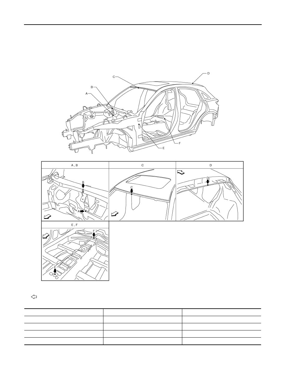
Body Center Marks
INFOID:0000000005248952
A mark is placed on each part of the body to indicate the vehicle center. When repairing the vehicle frame
(members, pillars, etc.) damaged by an accident which it enables more accurate and effective repair by using
these marks together with body alignment specifications.
Unit: mm (in)
: Vehicle front
Points
Portion
Marks
A
Upper dash
Embossment
B
Upper dash crossmember
Bead
C
Front roof
Embossment
D
Rear roof
Indent
JSKIA0660ZZ