Infiniti FX35, FX50 (S51). Manual - part 1948


  Index      Infiniti     Infiniti FX35, FX50 (S51) - service repair manual 2010 year


Search            


Content   ..  1946  1947  1948  1949   ..


Infiniti FX35, FX50 (S51). Manual - part 1948


REAR WIPER AND WASHER SYSTEM

WW-15

< SYSTEM DESCRIPTION >

C

D

E

F

G

H

I

J

K

M

A

B

WW

N

O

P

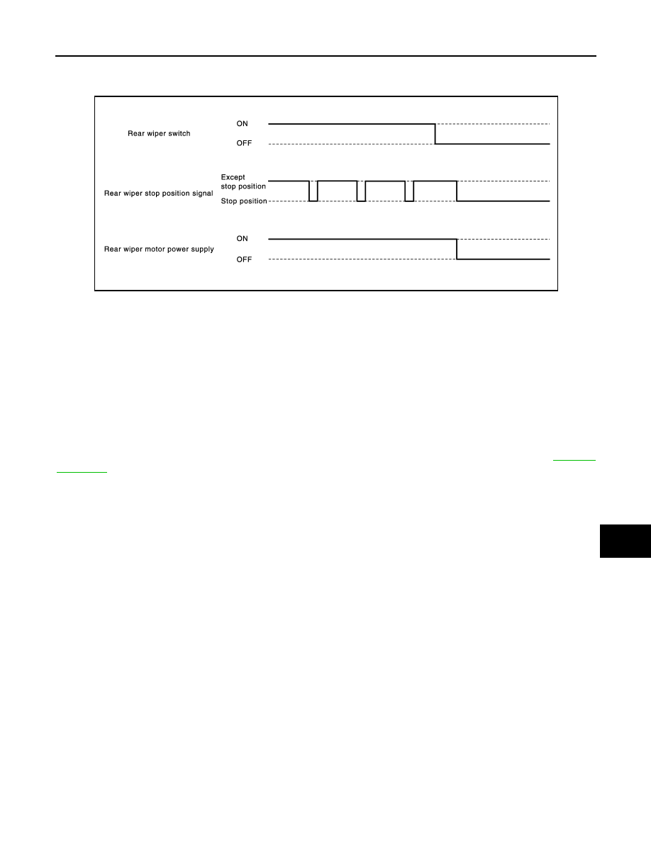
• BCM reads a stop position signal from the rear wiper motor to detect a rear wiper motor position.
• When the rear wiper motor is at other than the stopping position, BCM continues to supply power to the rear

wiper motor until it returns to the stopping position.

NOTE:
BCM stops supplying power to the rear wiper motor when the ignition switch is turned OFF.

REAR WIPER OPERATION LINKED WITH WASHER 

• BCM supplies power to the rear wiper motor according to the washer linked operating condition of rear

wiper. When the rear washer switch is turned OFF, BCM controls rear wiper to operate approximately 3
times.

Washer linked operating condition of rear wiper

- Ignition switch ON
- Rear washer switch ON (0.4 second or more)
• The washer pump is grounded through the combination switch with the rear washer switch ON.

REAR WIPER FAIL

SAFE OPERATION

BCM performs the fail-safe function when the rear wiper auto stop circuit is malfunctioning. Refer to 

BCS-75,

"Fail-safe"

.

JPLIA1259GB

WW-16

< SYSTEM DESCRIPTION >

REAR WIPER AND WASHER SYSTEM

Component Parts Location

INFOID:0000000005234744

Component Description

INFOID:0000000005234745

1.

Combination switch

2.

BCM

3.

Washer pump

4.

Rear wiper motor

A.

Dash side lower (Passenger side)

B.

Radiator core support (RH)

C.

Back door finisher inner inside

JPLIA1243ZZ

Part

Description

BCM

• Judges each switch status by the combination switch reading function.
• Supplies power to the rear wiper motor.
• Performs the auto stop control of the rear wiper.

Combination switch
(Wiper & washer switch)

Refer to 

BCS-8, "System Description"

.

DIAGNOSIS SYSTEM (BCM)

WW-17

< SYSTEM DESCRIPTION >

C

D

E

F

G

H

I

J

K

M

A

B

WW

N

O

P

DIAGNOSIS SYSTEM (BCM)

COMMON ITEM

COMMON ITEM : CONSULT-III Function (BCM - COMMON ITEM)

INFOID:0000000005605564

APPLICATION ITEM

CONSULT-III performs the following functions via CAN communication with BCM.

SYSTEM APPLICATION

BCM can perform the following functions for each system.
NOTE:
It can perform the diagnosis modes except the following for all sub system selection items.

×

: Applicable item

NOTE:

*: This item is displayed, but is not used. 

FREEZE FRAME DATA (FFD)

The BCM records the following vehicle condition at the time a particular DTC is detected, and displays on
CONSULT-III.

Diagnosis mode

Function Description

Work Support

Changes the setting for each system function.

Self Diagnostic Result

Displays the diagnosis results judged by BCM.

CAN Diag Support Monitor

Monitors the reception status of CAN communication viewed from BCM. Refer to CONSULT-III opera-
tion manual.

Data Monitor

The BCM input/output signals are displayed.

Active Test

The signals used to activate each device are forcibly supplied from BCM.

Ecu Identification

The BCM part number is displayed.

Configuration

• Read and save the vehicle specification.
• Write the vehicle specification when replacing BCM.

System

Sub system selection item

Diagnosis mode

Work Support

Data Monitor

Active Test

Door lock

DOOR LOCK

×

×

×

Rear window defogger

REAR DEFOGGER

×

×

Warning chime

BUZZER

×

×

Interior room lamp timer

INT LAMP

×

×

×

Exterior lamp

HEAD LAMP

×

×

×

Wiper and washer

WIPER

×

×

×

Turn signal and hazard warning lamps

FLASHER

×

×

×

AIR CONDITONER*

• Intelligent Key system
• Engine start system

INTELLIGENT KEY

×

×

×

Combination switch

COMB SW

×

Body control system

BCM

×

IVIS - NATS

IMMU

×

×

Interior room lamp battery saver

BATTERY SAVER

×

×

×

Back door open

TRUNK

×

×

Vehicle security system

THEFT ALM

×

×

×

RAP system

RETAINED PWR

×

Signal buffer system

SIGNAL BUFFER

×

×

WW-18

< SYSTEM DESCRIPTION >

DIAGNOSIS SYSTEM (BCM)

WIPER

WIPER : CONSULT-III Function (BCM - WIPER)

INFOID:0000000005234747

WORK SUPPORT

*:Factory setting

DATA MONITOR

CONSULT screen item

Indication/Unit

Description

Vehicle Speed

km/h

Vehicle speed of the moment a particular DTC is detected

Odo/Trip Meter

km

Total mileage (Odometer value) of the moment a particular DTC is detected

Vehicle Condition

SLEEP>LOCK

Power position status of 
the moment a particular 
DTC is detected

While turning BCM status from low power consumption mode to 
normal mode (Power supply position is “LOCK”)

SLEEP>OFF

While turning BCM status from low power consumption mode to 
normal mode (Power supply position is “OFF”.)

LOCK>ACC

While turning power supply position from “LOCK” to “ACC”

ACC>ON

While turning power supply position from “ACC” to “IGN”

RUN>ACC

While turning power supply position from “RUN” to “ACC” (Vehicle 
is stopping and selector lever is except P position.)

CRANK>RUN

While turning power supply position from “CRANKING” to “RUN” 
(From cranking up the engine to run it)

RUN>URGENT

While turning power supply position from “RUN“ to “ACC” (Emer-
gency stop operation)

ACC>OFF

While turning power supply position from “ACC” to “OFF”

OFF>LOCK

While turning power supply position from “OFF” to “LOCK”

OFF>ACC

While turning power supply position from “OFF” to “ACC”

ON>CRANK

While turning power supply position from “IGN” to “CRANKING”

OFF>SLEEP

While turning BCM status from normal mode (Power supply posi-
tion is “OFF”.) to low power consumption mode

LOCK>SLEEP

While turning BCM status from normal mode (Power supply posi-
tion is “LOCK”.) to low power consumption mode

LOCK

Power supply position is “LOCK” (Ignition switch OFF with steer-
ing is locked.)

OFF

Power supply position is “OFF” (Ignition switch OFF with steering 
is unlocked.)

ACC

Power supply position is “ACC” (Ignition switch ACC)

ON

Power supply position is “IGN” (Ignition switch ON with engine 
stopped)

ENGINE RUN

Power supply position is “RUN” (Ignition switch ON with engine 
running)

CRANKING

Power supply position is “CRANKING” (At engine cranking)

IGN Counter

0 - 39

The number of times that ignition switch is turned ON after DTC is detected
• The number is 0 when a malfunction is detected now.
• The number increases like 1 

 2 

 3...38 

 39 after returning to the normal condition 

whenever ignition switch OFF 

 ON.

• The number is fixed to 39 until the self-diagnosis results are erased if it is over 39.

Service item

Setting item

Description

WIPER SPEED 
SETTING

On

With vehicle speed
(Front wiper intermittent time linked with the vehicle speed and wiper intermittent dial position)

Off*

Without vehicle speed
(Front wiper intermittent time linked with the wiper intermittent dial position)


Content   ..  1946  1947  1948  1949   ..