Content .. 1898 1899 1900 1901 ..
Infiniti FX35, FX50 (S51). Manual - part 1900
WCS-20
< DTC/CIRCUIT DIAGNOSIS >
POWER SUPPLY AND GROUND CIRCUIT
DTC/CIRCUIT DIAGNOSIS
POWER SUPPLY AND GROUND CIRCUIT
COMBINATION METER
COMBINATION METER : Diagnosis Procedure
INFOID:0000000005524753
1.
CHECK FUSE
Check for blown fuses.
Is the inspection result normal?
YES
>> GO TO 2.
NO
>> Be sure to eliminate cause of malfunction before installing new fuse.
2.
CHECK POWER SUPPLY CIRCUIT
Check voltage between combination meter harness connector and ground.
Is the inspection result normal?
YES
>> GO TO 3.
NO
>> Check harness between combination meter and fuse.
3.
CHECK GROUND CIRCUIT
1.
Turn ignition switch OFF.
2.
Disconnect combination meter connector.
3.
Check continuity between combination meter harness connector and ground.
Is the inspection result normal?
YES
>> INSPECTION END
NO
>> Repair harness or connector.
UNIFIED METER AND A/C AMP.
UNIFIED METER AND A/C AMP. : Diagnosis Procedure
INFOID:0000000005524754
1.
CHECK FUSE
Check for blown fuses.
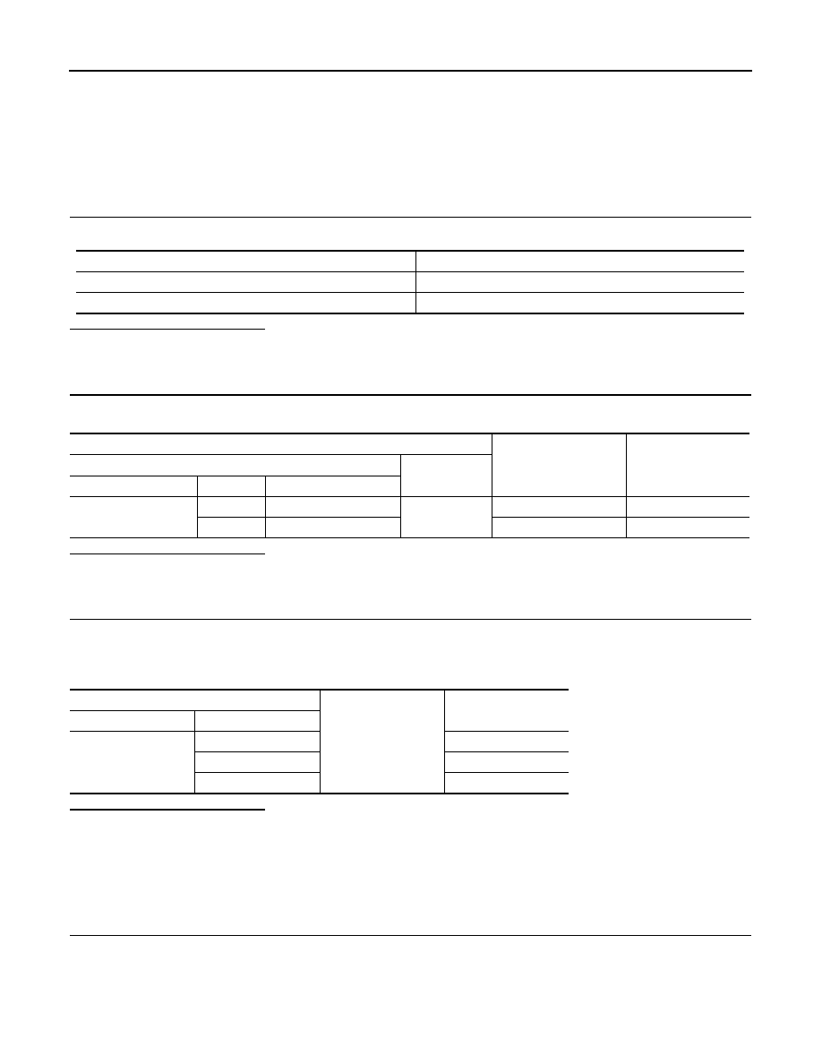
Power source
Fuse No.
Battery
11
Ignition switch ON or START
4
Terminals
Ignition switch position
Value (Approx.)
(+)
(-)
Combination meter
Terminal
Signal name
M53
1
Battery power supply
Ground
OFF
Battery voltage
21
Ignition signal
ON
Battery voltage
Combination meter
Ground
Continuity
Connector
Terminal
M53
5
Existed
15
Existed
22
Existed