Infiniti FX35, FX50 (S51). Manual - part 1889


  Index      Infiniti     Infiniti FX35, FX50 (S51) - service repair manual 2010 year


Search            


Content   ..  1887  1888  1889  1890   ..


Infiniti FX35, FX50 (S51). Manual - part 1889


TRANSMISSION ASSEMBLY

TM-363

< UNIT REMOVAL AND INSTALLATION >

[7AT: RE7R01B (VK50VE)]

C

E

F

G

H

I

J

K

L

M

A

B

TM

N

O

P

• Never disassemble.
• Never allow metal filings, etc. to get on the sensor's front edge magnetic area.
• Never place in an area affected by magnetism.

8.

Remove rear plate cover. Refer to 

EM-188, "Exploded View"

.

9.

Turn crankshaft, and remove the four tightening bolts for drive plate and torque converter.

CAUTION:

When turning the crankshaft, turn it clockwise as viewed from the front of the engine.

10. Remove A/T fluid cooler tube from the A/T assembly and engine. Refer to 

TM-359, "Exploded View"

.

11. Plug up openings such as the A/T fluid cooler tube hole.
12. Support A/T assembly with a transmission jack.

CAUTION:

When setting the transmission jack, be careful not to allow it to collide against the drain plug.

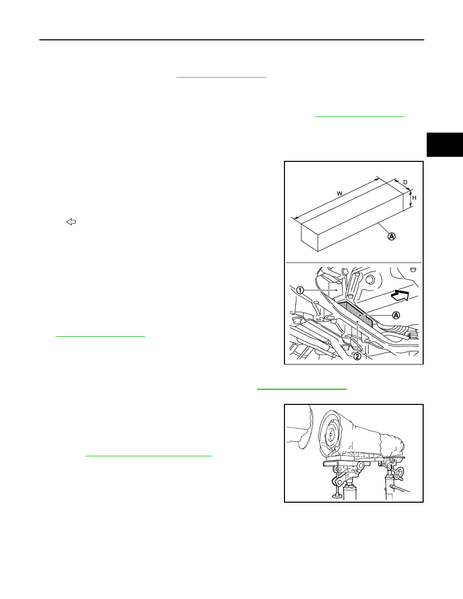
13. Insert a wooden block (A) between oil pan (upper) (1) of engine

and front suspension member (2). 

CAUTION:

• Always insert a wooden block between oil pan (upper)  of

engine and front suspension member when removing A/T
assembly from the engine.  (Because VVEL control shaft
position sensor may be damaged by the interference
between VVEL control shaft position sensor and dash
panel if the operation is performed without the wooden
block inserted.)

• After inserting wooden block, check it does not fall out

easily.

14. Remove rear engine mounting member with power tool. Refer to

EM-196, "Exploded View"

.

15. Disconnect A/T assembly connector and AWD solenoid connec-

tor.

16. Remove harness and brackets.

17. Remove bolts fixing A/T assembly to engine with power tool.

18. Remove air breather hose and air breather vent. Refer to 

TM-357, "Exploded View"

.

19. Remove A/T assembly with transfer assembly from vehicle.

CAUTION:

• Secure torque converter to prevent it from dropping.
• Secure A/T assembly to a transmission jack.

20. Remove transfer assembly from A/T assembly with power tool.

Refer to 

DLN-67, "VK50VE : Exploded View"

.

INSTALLATION

Note the following, and install in the reverse order of removal.

CAUTION:

W

: 150 mm (5.91 in)

D

: 30 mm (1.18 in)

H

: 20 mm (0.79 in)

: Vehicle front

JPDIA0923ZZ

SCIA2203E

TM-364

< UNIT REMOVAL AND INSTALLATION >

[7AT: RE7R01B (VK50VE)]

TRANSMISSION ASSEMBLY

Check fitting of dowel pin (

).

• When installing A/T assembly to the engine, be sure to check

dimension “A” to ensure it is within the reference value limit.

• When installing A/T assembly to the engine, attach the fixing bolts

in accordance with the following standard.

*: Tightening the bolt with air breather vent and spring washer.

• Align the positions of tightening bolts for drive plate with those of the torque converter, and temporarily

tighten the bolts. Then, tighten the bolts with the specified torque.

CAUTION:

• When turning crankshaft, turn it clockwise as viewed from the front of the engine.
• When tightening the tightening bolts for the torque converter after fixing the crankshaft pulley

bolts, be sure to confirm the tightening torque of the crankshaft pulley mounting bolts. Refer to

EM-212, "Exploded View"

.

• Rotate crankshaft several turns and check to be sure that A/T rotates freely without binding after

converter is installed to drive plate.

Inspection and Adjustment

INFOID:0000000005250366

INSPECTION AFTER INSTALLATION

Check A/T fluid leakage.
Check A/T position after adjusting A/T positions. Refer to 

TM-349, "Inspection and Adjustment"

.

ADJUSTMENT AFTER INSTALLATION

Adjust A/T fluid level. Refer to 

TM-343, "Adjustment"

.

Adjust A/T position. Refer to 

TM-349, "Inspection and Adjustment"

.

JPDIA0899ZZ

B

:  Scale

C

: Straightedge

Dimension “A”

: Refer to 

TM-366, "Torque Convert-

er"

.

JPDIA0042ZZ

Bolt symbol

A

B

*

C

Insertion direction

A/T assembly to engine

Number of bolts

5

1

4

Bolt length (L)
mm (in)

70 (2.76)

65 (2.56)

Tightening torque
N·m (kg-m, ft-lb)

113 (12, 83)

74 (7.5, 55)

JPDIA0852ZZ

SERVICE DATA AND SPECIFICATIONS (SDS)

TM-365

< SERVICE DATA AND SPECIFICATIONS (SDS) 

[7AT: RE7R01B (VK50VE)]

C

E

F

G

H

I

J

K

L

M

A

B

TM

N

O

P

SERVICE DATA AND SPECIFICATIONS (SDS)

SERVICE DATA AND SPECIFICATIONS (SDS)

General Specification

INFOID:0000000005250367

*1: Refer to 

MA-12, "Fluids and Lubricants"

.

*2: The fluid capacity is the reference value.

Vehicle Speed at Which Gear Shifting Occurs

INFOID:0000000005250368

Unit: km/h (MPH)

• At half throttle, the accelerator opening is 4/8 of the full opening.

Transmission model code number

1XR4A

Stall torque ratio

1.93 : 1

Transmission gear ratio

1st

4.887

2nd

3.170

3rd

2.027

4th

1.412

5th

1.000

6th

0.864

7th

0.775

Reverse

4.041

Recommended fluid

Genuine NISSAN Matic S ATF

*1

Fluid capacity

11.3 liter (12 US qt, 10 Imp qt)

*2

CAUTION:

• Use only Genuine NISSAN Matic S ATF. Never mix with other ATF.
• Using ATF other than Genuine NISSAN Matic S ATF will cause deterioration driveability and A/T durability, and may damage 

the A/T, which is not covered by the INFINITI new vehicle limited warranty.

Gear position

Throttle position

Full throttle 

Half throttle 

D

 D

2

50 – 54 (32 – 33)

19 – 23 (12 – 14)

D

 D

3

79 – 87 (50 – 54)

41 – 49 (26 – 30)

D

 D

4

126 – 136 (79 – 84)

68 – 78 (43 – 48)

D

 D

5

181 – 191 (113 – 118)

99 – 109 (62 – 67)

D

 D

6

235 – 245 (147 – 152)

155 – 165 (97 – 102)

D

 D

7

250 – 260 (156 – 161)

206 – 216 (129 – 134)

D

 D

6

240 – 250 (150 – 155)

162 – 172 (101 – 106)

D

 D

5

219 – 229 (137 – 142)

105 – 115 (66 – 71)

D

 D

4

165 – 175 (103 – 108)

53 – 63 (33 – 39)

D

 D

3

110 – 120 (69 – 74)

31 – 41 (20 – 25)

D

 D

2

40 – 48 (25 – 29)

16 – 24 (10 – 14)

D

 D

1

16 – 20 (10 – 12)

7 – 11 (5 – 6)

TM-366

< SERVICE DATA AND SPECIFICATIONS (SDS) 

[7AT: RE7R01B (VK50VE)]

SERVICE DATA AND SPECIFICATIONS (SDS)

Vehicle Speed at Which Lock-up Occurs/Releases

INFOID:0000000005250369

• At closed throttle, the accelerator opening is less than 1/8 condition. (Closed throttle position signal OFF)

• At half throttle, the accelerator opening is 4/8 of the full opening.

Stall Speed

INFOID:0000000005250370

Torque Converter

INFOID:0000000005250373

Throttle position

Vehicle speed

km/h (MPH)

Lock-up ON

Lock-up OFF

Closed throttle

47 – 55 (30 – 34)

44 – 52 (28 – 32)

Half throttle

60 – 68 (38 – 42)

57 – 65 (36 – 40)

Stall speed

2,467 – 2,767 rpm

Dimension between end of converter housing and torque converter

24.0 mm (0.94 in)


Content   ..  1887  1888  1889  1890   ..