Infiniti FX35, FX50 (S51). Manual - part 1886


  Index      Infiniti     Infiniti FX35, FX50 (S51) - service repair manual 2010 year


Search            


Content   ..  1884  1885  1886  1887   ..


Infiniti FX35, FX50 (S51). Manual - part 1886


A/T SHIFT SELECTOR

TM-351

< REMOVAL AND INSTALLATION >

[7AT: RE7R01B (VK50VE)]

C

E

F

G

H

I

J

K

L

M

A

B

TM

N

O

P

Removal and Installation

INFOID:0000000005250349

REMOVAL

1.

Shift the selector lever to “P” position.

2.

Remove control rod from A/T shift selector.

3.

Shift the selector lever to “N” position.

4.

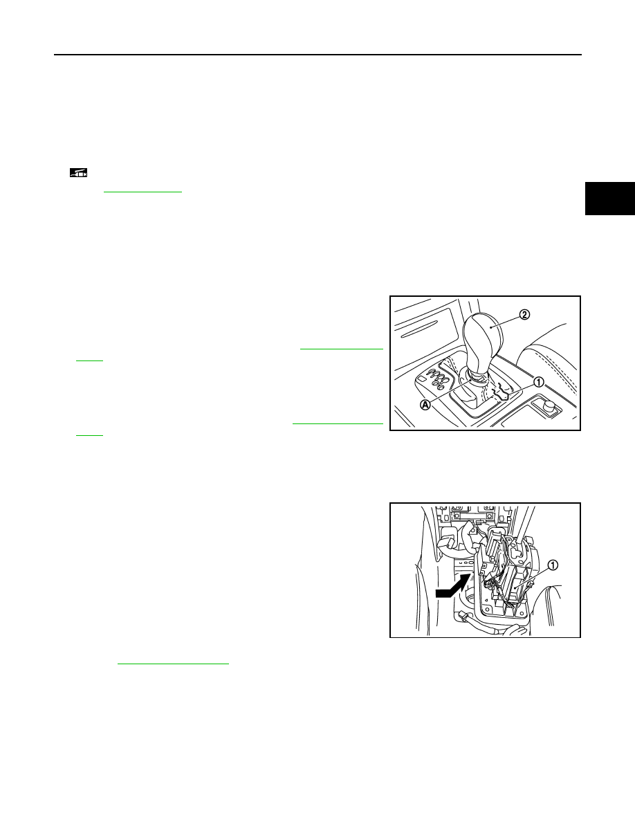
Remove knob cover (A) below selector lever downward.

5.

Pull lock pin (1) out of selector lever knob (2).

6.

Remove selector lever knob.

7.

Remove center console assembly. Refer to 

IP-22, "Exploded

View"

.

CAUTION:

When disconnecting selector lever position indicator con-
nector from shift position switch, never twist or apply an
excessive load to the connector.

8.

Remove the rear ventilator duct 1. Refer to 

VTL-11, "Exploded

View"

.

9.

Disconnect A/T shift selector connector.

10. Remove harness clips from A/T shift selector assembly.

11. Shift the selector lever to “P” position.
12. Remove A/T shift selector assembly mounting bolts.

13. Slightly lift the A/T shift selector assembly (1) and slide it right-

ward. Then pull it out in the diagonally right direction.

14. Remove adapter from A/T shift selector assembly.

15. Remove dust cover and dust cover plate from A/T shift selector

assembly.

16. Remove dust cover from dust cover plate.

17. Remove shift lock unit from A/T shift selector assembly.

18. Remove brackets from vehicle floor panel.

19. Remove selector lever position indicator from console finisher

assembly:

a.

Remove indicator assembly from console finisher assembly.
Refer to 

IP-22, "Exploded View"

.

b.

Remove insert finisher from indicator assembly.

c.

Remove selector lever position indicator.

INSTALLATION

Note the following, and install in the reverse order of removal.

CAUTION:

Apply multi-purpose grease on the pin surface (that slides after installing a collar) of the pivot pin.
• Refer to the followings when installing selector lever knob to A/T shift selector assembly.
1.

Insert lock pin to selector lever knob.

2.

Install selector lever knob over selector lever until a click is felt.

1.

Selector lever knob

2.

Lock pin

3.

Indicator plate

4.

Selector lever position indicator

5.

Harness connector

6.

Insert finisher

7.

Control rod

8.

Dust cover

9.

Bracket

10.

Dust cover plate

11.

Snap pin

12.

Washer

13.

Collar

14.

Clip

15.

Pivot pin

16.

Insulator

17.

Shift lock unit

18.

A/T shift selector assembly

19.

Adapter

: Apply multi-purpose grease.

Refer to 

GI-4, "Components"

 for symbols not described on the above.

JPDIA0898ZZ

JPDIA0055ZZ

TM-352

< REMOVAL AND INSTALLATION >

[7AT: RE7R01B (VK50VE)]

A/T SHIFT SELECTOR

CAUTION:

• Install it straight, and never tap or apply any shock to install it.
• Never push selector button.

• When installing control rod to A/T shift selector assembly, refer to “ADJUSTMENT”. Refer to 

TM-349,

"Inspection and Adjustment"

.

Inspection and Adjustment

INFOID:0000000005250350

INSPECTION AFTER INSTALLATION

Check A/T positions after adjusting A/T positions. Refer to 

TM-349, "Inspection and Adjustment"

.

ADJUSTMENT AFTER INSTALLATION

Adjust A/T positions. Refer to 

TM-349, "Inspection and Adjustment"

.

CONTROL ROD

TM-353

< REMOVAL AND INSTALLATION >

[7AT: RE7R01B (VK50VE)]

C

E

F

G

H

I

J

K

L

M

A

B

TM

N

O

P

CONTROL ROD

Exploded View

INFOID:0000000005250351

Removal and Installation

INFOID:0000000005250352

REMOVAL

1.

Shift the selector lever to “P” position.

2.

Disconnect A/T shift selector and control rod. Refer to 

TM-350, "Exploded View"

.

3.

Remove manual lever from A/T assembly.

4.

Remove control rod from manual lever.

INSTALLATION

Note the following, and install in the reverse order of removal.

CAUTION:

Apply multi-purpose grease on the pin surface (that slides after installing collar) of the tip of the con-
trol rod.
• When installing control rod to A/T shift selector assembly, refer to “ADJUSTMENT”. Refer to 

TM-349,

"Inspection and Adjustment"

.

Inspection

INFOID:0000000005250353

INSPECTION AFTER INSTALLATION

Check A/T positions after adjusting A/T positions. Refer to 

TM-349, "Inspection and Adjustment"

.

ADJUSTMENT AFTER INSTALLATION

Adjust A/T positions. Refer to 

TM-349, "Inspection and Adjustment"

.

1.

A/T assembly

2.

Manual lever

3.

Lock washer

4.

Control rod

5.

Washer

6.

Insulator

7.

Collar

8.

Conical washer

9.

Snap pin

: Apply multi-purpose grease.

Refer to 

GI-4, "Components"

 for symbols not described on the above.

JSDIA1002GB

TM-354

< REMOVAL AND INSTALLATION >

[7AT: RE7R01B (VK50VE)]

PADDLE SHIFTER

PADDLE SHIFTER

Exploded View

INFOID:0000000005250354

Removal and Installation

INFOID:0000000005250355

REMOVAL

1.

Remove steering column cover. Refer to 

IP-11, "Exploded View"

.

2.

Disconnect paddle shifter connectors from each paddle shifter.

3.

Remove paddle shifter mounting bolts and nuts.

4.

Remove each paddle shifter from steering column assembly.

INSTALLATION

Install in the reverse order of removal.

1.

Steering column assembly

2.

Paddle shifter (shift-down)

3.

Paddle shifter (shift-up)

Refer to 

GI-4, "Components"

 for symbols in the figure.

JPDIA0051GB


Content   ..  1884  1885  1886  1887   ..