Content .. 1839 1840 1841 1842 ..
Infiniti FX35, FX50 (S51). Manual - part 1841
CONTROL ROD
TM-171
< REMOVAL AND INSTALLATION >
[7AT: RE7R01A (VQ35HR)]
C
E
F
G
H
I
J
K
L
M
A
B
TM
N
O
P
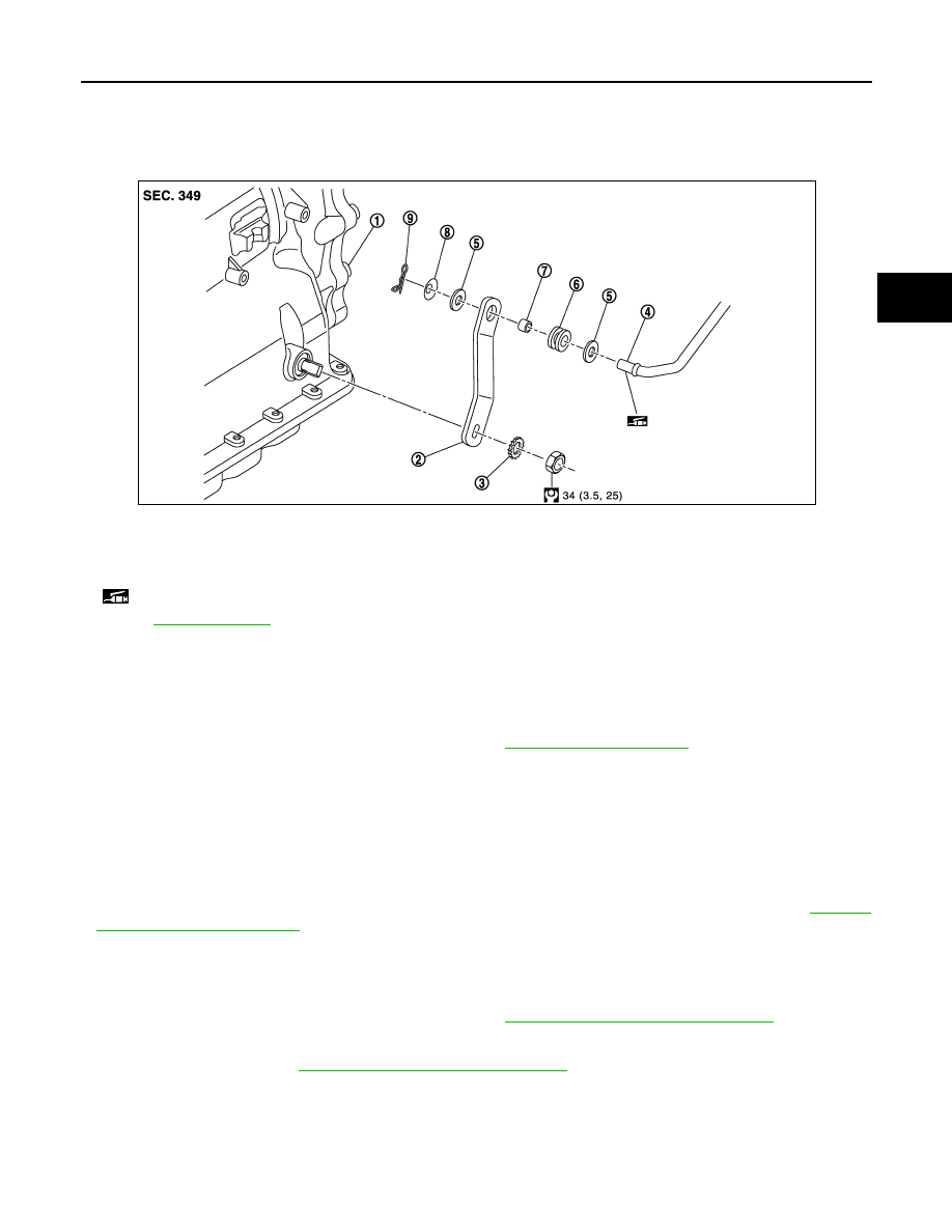
CONTROL ROD
Exploded View
INFOID:0000000005250154
Removal and Installation
INFOID:0000000005250155
REMOVAL
1.
Shift the selector lever to “P” position.
2.
Disconnect A/T shift selector and control rod. Refer to
.
3.
Remove manual lever from A/T assembly.
4.
Remove control rod from manual lever.
INSTALLATION
Note the following, and install in the reverse order of removal.
CAUTION:
Apply multi-purpose grease on the pin surface (that slides after installing collar) of the tip of the con-
trol rod.
• When installing control rod to A/T shift selector assembly, refer to “ADJUSTMENT”. Refer to
.
Inspection and Adjustment
INFOID:0000000005250156
INSPECTION AFTER INSTALLATION
Check A/T positions after adjusting A/T positions. Refer to
TM-349, "Inspection and Adjustment"
ADJUSTMENT AFTER INSTALLATION
Adjust A/T positions. Refer to
TM-349, "Inspection and Adjustment"
1.
A/T assembly
2.
Manual lever
3.
Lock washer
4.
Control rod
5.
Washer
6.
Insulator
7.
Collar
8.
Conical washer
9.
Snap pin
: Apply multi-purpose grease.
for symbols not described on the above.
JSDIA1002GB