Infiniti FX35, FX50 (S51). Manual - part 1813


  Index      Infiniti     Infiniti FX35, FX50 (S51) - service repair manual 2010 year


Search            


Content   ..  1811  1812  1813  1814   ..


Infiniti FX35, FX50 (S51). Manual - part 1813


SHIFT LOCK SYSTEM

TM-59

< SYSTEM DESCRIPTION >

[7AT: RE7R01A (VQ35HR)]

C

E

F

G

H

I

J

K

L

M

A

B

TM

N

O

P

SHIFT LOCK SYSTEM

System Description

INFOID:0000000005250019

• Shift lock prevents an unintentional start of the vehicle that may be caused by an incorrect operation while

selector lever is in the “P” position.

• Selector lever can be shifted from the “P” position to another position when the following conditions are sat-

isfied.

- Ignition switch ON
- Stop lamp switch is ON (brake pedal is depressed)
- Selector lever knob button is pressed

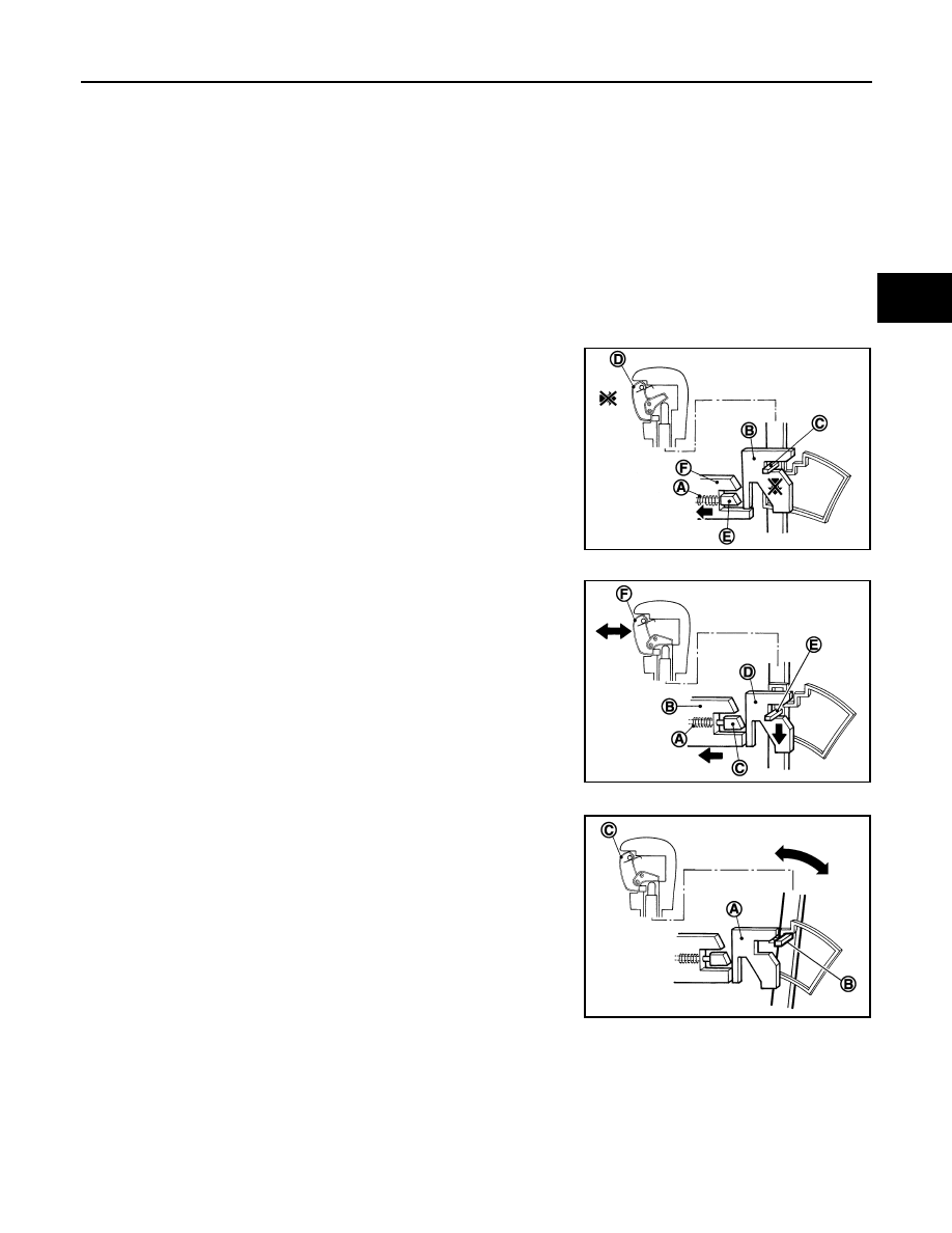
SHIFT LOCK OPERATION AT “P” POSITION

When Brake Pedal Is Not Depressed (No Shift Operation Allowed)

The shift lock solenoid (A) inside the shift lock unit is not energized if
the brake pedal is not depressed while the ignition switch is ON.
The lock plate (B) lowers according to the downward movement of
the position pin (C) when the selector button (D) is pressed, and
presses only slider B (E) into the shift lock unit. Slider A (F) located
below the lock plate prevents the downward movement of the lock
plate with the spring force. The selector lever cannot be shifted from
the “P” position for this reason.
However, slider A is forcibly pressed into the shift lock unit, allowing
the selector lever to shift if the shift lock release button is pressed.

When Brake Pedal Is Depressed (Shift Operation Allowed)

The shift lock solenoid (A) inside the shift lock unit is energized and
the relative positions of sliders A (B) and B (C) are maintained when
the brake pedal is depressed while the ignition switch is ON.
The lock plate (D) lowers according to the downward movement of
the position pin (E), thrusting away sliders A and B, when the selec-
tor button (F) is pressed.
The position pin lowers to the position that allows shift operation for
this reason. As a result, the selector lever can be shifted out of the P
position.

OPERATION AT OTHER THAN “P” POSITION

The shift lock function will not operate at any position other than “P”
because the lock plate (A) is only set for the “P” position. Accord-
ingly, the selector lever can be shifted to any position regardless of
the brake operation.
The position pin (B) enters the “P” position thrusting away the lock
plate when the selector lever is shifted to the “P” position. Then, the
shift mechanism is locked when the selector button (C) is released.

“P” POSITION RETAINING MECHANISM (IGNITION SWITCH LOCK)

When ignition switch is not in the ON position, power is not applied to the shift lock solenoid in the shift lock
unit. This causes shift lock state, and then “P” position is retained.
When an actuating system in the shift lock unit has a malfunction, selector lever is unable to operate from the
“P” position even when pressing the brake pedal with the ignition switch ON. However, when pressing the shift
lock release button, slider A is forcibly pressed into the shift lock unit. This allows shift lock to be released and
selector lever enables the select operation from the “P” position.

CAUTION:

JSDIA0119ZZ

JSDIA0120ZZ

JSDIA0121ZZ

TM-60

< SYSTEM DESCRIPTION >

[7AT: RE7R01A (VQ35HR)]

SHIFT LOCK SYSTEM

Never use the shift lock release button except when the select lever is inoperative even when pressing
the brake pedal with the ignition switch ON.

Component Parts Location

INFOID:0000000005250020

*: Shift lock release button becomes operative by removing shift lock cover.

Component Description

INFOID:0000000005530854

1.

Position pin

2.

Shift lock unit

3.

Shift lock solenoid

4.

Slider A

5.

A/T shift selector connector

6.

Lock plate

7.

Slider B

8.

Stop lamp switch

9.

Brake pedal

10. Shift lock cover *

A.

A/T shift selector assembly

B.

Brake pedal, upper

C.

Center console

JSDIA1461ZZ

Component

Function

Shift lock unit

Shift lock solenoid

Activated by the ignition switch and stop lamp signals, it holds the relative 
positions of sliders A and B.

Lock plate

Restricts position pin moving.

Shift lock release button

Pressing the shift lock release button cancels the shift lock forcibly.

Position pin

Links with selector knob button and restricts selector lever shift operation.

Stop lamp switch

• When brake pedal is depressed, stop lamp switch turns ON.
• When stop lamp switch turns ON, power is supplied to shift lock unit.

ON BOARD DIAGNOSTIC (OBD) SYSTEM

TM-61

< SYSTEM DESCRIPTION >

[7AT: RE7R01A (VQ35HR)]

C

E

F

G

H

I

J

K

L

M

A

B

TM

N

O

P

ON BOARD DIAGNOSTIC (OBD) SYSTEM

Diagnosis Description

INFOID:0000000005250022

The A/T system has two self-diagnostic systems.
The first is the emission-related on board diagnostic system (OBD-II) performed by the TCM in combination
with the ECM. A malfunction is indicated by the MIL (malfunction indicator lamp) and is stored as a DTC in the
ECM memory and in the TCM memory.
The second is the TCM original self-diagnosis indicated by the TCM. A malfunction history is stored in the
TCM memory. The detected items are overlapped with OBD-II self-diagnostic items. For details, refer to 

EC-

541, "DTC Index"

.

OBD FUNCTION

The ECM provides emission-related on board diagnostic (OBD-II) functions for the A/T system.
One function is to receive a signal from the TCM used with OBD-related parts of the A/T system. The signal is
sent to the ECM when a malfunction occurs in the corresponding OBD-related part.
The other function is to indicate a diagnostic result by means of the MIL (malfunction indicator lamp) on the
instrument panel. Sensors, switches and solenoid valves are used as sensing elements.
The MIL automatically illuminates in “One or Two Trip Detection Logic” when a malfunction is sensed in rela-
tion to A/T system parts. For details, refer to 

EC-111, "Diagnosis Description"

.

TM-62

< SYSTEM DESCRIPTION >

[7AT: RE7R01A (VQ35HR)]

DIAGNOSIS SYSTEM (TCM)

DIAGNOSIS SYSTEM (TCM)

CONSULT-III Function (TRANSMISSION)

INFOID:0000000005250023

CONSULT-III APPLICATION ITEMS

*: Although “Function Test” and “Special Function” are selectable, do not use its.

SELF-DIAGNOSTIC RESULTS

Display Items List

Refer to 

TM-150, "DTC Index"

.

DATA MONITOR

Display Items List

 X: Standard, —: Not applicable, 

: Option

Diagnostic test mode

Function

Self Diagnostic Results

Retrieve DTC from ECU and display diagnostic items.

Data Monitor

Monitor the input/output signal of the control unit in real time.

CAN Diagnosis

This mode displays a network diagnosis result about CAN by a diagram.

CAN Diagnostic Support 
Monitor

It monitors the starts of CAN communication.

DTC & SRT confirmation

The status of system monitoring tests and the self-diagnosis status/result can be confirmed.

ECU Identification

Display the ECU identification number (part number etc.) of the selected system.

Function Test*

This mode can show results of self-diagnosis of ECU with either “OK” or “NG”. For engine, more prac-
tical tests regarding sensors/switches and/or actuators are available.

Special Function*

Other results or histories, etc. that are recorded in ECU are displayed.

Monitored item (Unit)

Monitor Item Selection

Remarks

ECU IN-

PUT SIG-

NALS

MAIN 

SIGNALS

SELEC-

TION 

FROM 

ITEM

VHCL/S SE-A/T

(km/h or mph)

X

X

Displays the vehicle speed calculated by the 
TCM from the output shaft revolution.

ESTM VSP SIG

(km/h or mph)

X

Displays the vehicle speed signal received via 
CAN communication.

OUTPUT REV

(rpm)

X

X

Displays the output shaft revolution calculated 
from the pulse signal of output speed sensor.

INPUT SPEED

(rpm)

X

X

Displays the input shaft revolution calculated 
from front sun gear revolution and front carrier 
revolution.

F SUN GR REV

(rpm)

Displays the front sun gear revolution calculated 
from the pulse signal of input speed sensor 1.

F CARR GR REV

(rpm)

Displays the front carrier gear revolution calculat-
ed from the pulse signal of input speed sensor 2.

ENGINE SPEED

(rpm)

X

X

Displays the engine speed received via CAN 
communication.

TC SLIP SPEED

(rpm)

X

Displays the revolution difference between input 
speed and engine speed.

ACCELE POSI

(0.0/8)

X

Displays the accelerator position estimated value 
received via CAN communication.

THROTTLE POSI

(0.0/8)

X

X

Displays the throttle position received via CAN 
communication.


Content   ..  1811  1812  1813  1814   ..