Content .. 1774 1775 1776 1777 ..
Infiniti FX35, FX50 (S51). Manual - part 1776
C1902, C1903, C1904, C1910, C1913 RAS MOTOR OUTPUT
STC-45
< DTC/CIRCUIT DIAGNOSIS >
[WITH REAR ACTIVE STEER]
C
D
E
F
H
I
J
K
L
M
A
B
STC
N
O
P
5.
Check the continuity between RAS control unit harness connector and ground.
Is the inspection result normal?
YES
>> GO TO 2.
NO
>> Repair or replace the harnesses and connectors.
2.
CHECK RAS MOTOR
Check RAS motor. Refer to
STC-46, "Component Inspection"
Is the inspection result normal?
YES
>> GO TO 3.
NO
>> Replace RAS actuator assembly. Refer to
.
3.
PERFORM ACTIVE TEST
With CONSULT-III
1.
Connect RAS control unit harness connector.
2.
Connect RAS motor harness connector.
3.
Perform “SELF DIAGNOSTIC MODE” item on “ACTIVE TEST” of “4WAS(MAIN)/RAS/HICAS”.
CAUTION:
Perform the active test while vehicle is stopped.
4.
Check “MOTOR VOLTAGE”, “MOTOR CURRENT” and “MTR CRNT OPE” while performing the active
test.
Without CONSULT-III
1.
Disconnect RAS control unit harness connector.
2.
Disconnect RAS motor harness connector.
3.
Start the engine.
4.
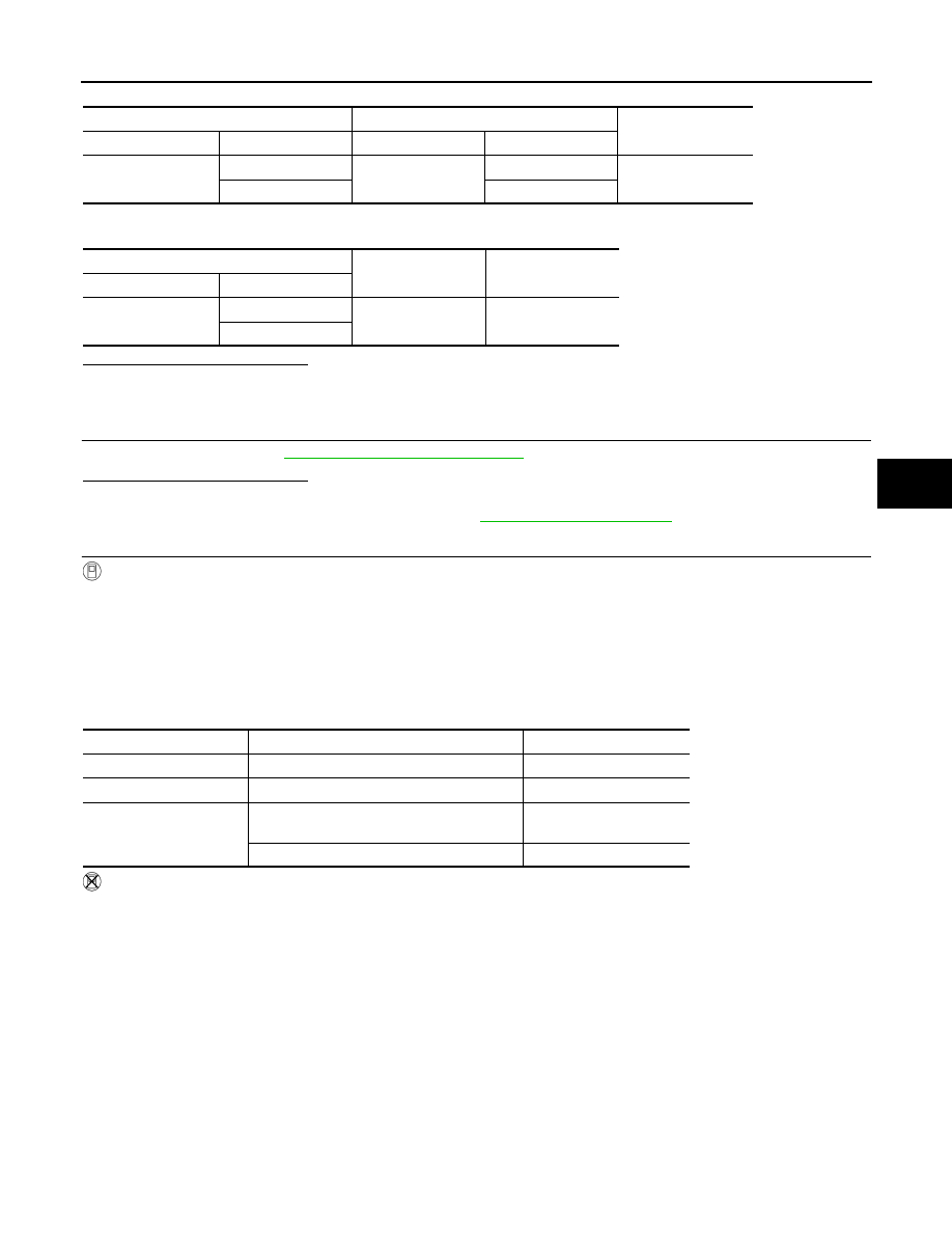
Check the voltage between RAS control unit harness connector and ground.
RAS control unit
RAS motor
Continuity
Connector
Terminal
Connector
Terminal
B37
38
B54
1
Existed
39
2
RAS control unit
—
Continuity
Connector
Terminal
B37
38
Ground
Not existed
39
Monitor item
Condition
Display value
MOTOR VOLTAGE
Ignition switch: ON
Battery voltage
MOTOR CURRENT
RAS motor running
0 – 20 A
MTR CRNT OPE
RAS actuator neutral condition and vehicle
straight-ahead position
Approx.
−
2 – 2 A
RAS motor running
Approx.
−
20 – 20 A