Infiniti FX35, FX50 (S51). Manual - part 1767


  Index      Infiniti     Infiniti FX35, FX50 (S51) - service repair manual 2010 year


Search            


Content   ..  1765  1766  1767  1768   ..


Infiniti FX35, FX50 (S51). Manual - part 1767


POWER STEERING SOLENOID VALVE

STC-9

< DTC/CIRCUIT DIAGNOSIS >

[WITHOUT REAR ACTIVE STEER]

C

D

E

F

H

I

J

K

L

M

A

B

STC

N

O

P

POWER STEERING SOLENOID VALVE

Description

INFOID:0000000005235339

Power steering solenoid valve controls the power steering oil pressure in the gear housing assembly.

Diagnosis Procedure

INFOID:0000000005235340

1.

CHECK POWER STEERING SOLENOID VALVE SIGNAL

1.

Turn the ignition switch OFF.

2.

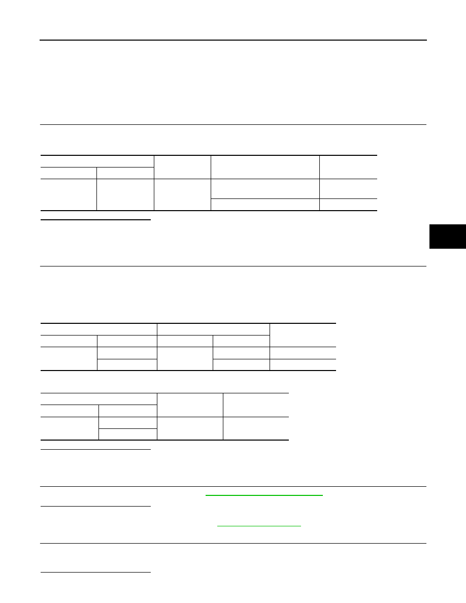
Check voltage between power steering control unit harness connector and ground.

Is the inspection result normal?

YES

>> GO TO 2.

NO

>> GO TO 4.

2.

CHECK HARNESS BETWEEN POWER STEERING SOLENOID VALVE AND POWER STEERING CON-

TROL UNIT

1.

Turn the ignition switch OFF.

2.

Disconnect power steering solenoid valve harness connector.

3.

Disconnect power steering control unit harness connector.

4.

Check the continuity between power steering solenoid valve harness connector and the power steering
control unit harness connector.

5.

Check continuity between power steering control unit harness connector and ground.

Is the inspection result normal?

 YES

>> GO TO 3.

 NO

>> Repair or replace damaged parts.

3.

CHECK POWER STEERING SOLENOID VALVE

Check power steering solenoid valve. Refer to 

STC-10, "Component Inspection"

Is the inspection result normal?

 YES

>> GO TO 4.

 NO

>> Replace gear-sub assembly. Refer to 

ST-26, "Exploded View"

.

4.

CHECK TERMINALS AND HARNESS CONNECTORS

• Check power steering control unit pin terminals for damage or loose connection with harness connector.
• Check power steering solenoid valve pin terminals for damage or loose connection with harness connector.

Is the inspection result normal?

Power steering control unit

Condition

Voltage (Approx.)

Connector

Terminal

M108

 1 

Ground

Vehicle speed: 0 km/h (0 MPH)
(Engine is running)

4.4 – 6.6 V

Vehicle speed: 100 km/h (62 MPH)

2.4 – 3.6 V

Power steering solenoid valve

Power steering control unit

Continuity

Connector

Terminal

Connector

Terminal

F45

1

M108

1

Existed

2

5

Existed

Power steering control unit

Continuity

Connector

Terminal

M108

1

Ground

Not existed

5

STC-10

< DTC/CIRCUIT DIAGNOSIS >

[WITHOUT REAR ACTIVE STEER]

POWER STEERING SOLENOID VALVE

YES

>> INSPECTION END

NO

>> Repair or replace damaged parts.

Component Inspection

INFOID:0000000005235341

1.

CHECK POWER STEERING SOLENOID VALVE

1.

Turn the ignition switch OFF.

2.

Disconnect power steering solenoid valve harness connector.

3.

Check resistance between power steering solenoid valve connector terminals.

4.

Check power steering solenoid valve by listening for its operation sound while applying battery voltage to
power steering solenoid valve connector F45 terminals 1 (positive) and 2 (negative).

Is the inspection result normal?

 YES

>> INSPECTION END

 NO

>> Replace gear-sub assembly. Refer to 

ST-26, "Exploded View"

.

Power steering solenoid valve

Resistance (Approx.)

Terminal

1 2

– 

ENGINE SPEED SIGNAL CIRCUIT

STC-11

< DTC/CIRCUIT DIAGNOSIS >

[WITHOUT REAR ACTIVE STEER]

C

D

E

F

H

I

J

K

L

M

A

B

STC

N

O

P

ENGINE SPEED SIGNAL CIRCUIT

Description

INFOID:0000000005235342

ECM sends engine speed signal to power steering control unit.

Diagnosis Procedure

INFOID:0000000005235343

1.

PERFORM ECM SELF-DIAGNOSIS

With CONSULT-III

1.

Turn the ignition switch ON.

2.

Perform “ENGINE” self-diagnosis. Refer to 

EC-124, "CONSULT-III Function"

 (VQ35HR), 

EC-718, "CON-

SULT-III Function"

 (VK50VE).

Is any DTC detected?

YES

>> Check the DTC.

NO

>> GO TO 2.

2.

CHECK HARNESS BETWEEN ECM AND POWER STEERING CONTROL UNIT

1.

Turn the ignition switch OFF.

2.

Disconnect ECM harness connectors.

3.

Disconnect power steering control unit harness connector.

4.

Check continuity between ECM harness connector and power steering control unit harness connector.

5.

Check continuity between power steering control unit harness connector and ground.

Is the inspection result normal?

YES

>> GO TO 3.

NO

>> Repair or replace damaged parts.

3.

CHECK ENGINE SPEED SIGNAL (1)

1.

Connect ECM harness connectors.

2.

Check signal between ECM harness connector and ground with oscilloscope.

ECM

Power steering control unit

Continuity

Connector

Terminal

Connector

Terminal

M107 (VQ35HR)

110

M108

10

Existed

M160 (VK50VE)

97

Power steering control unit

Continuity

Connector

Terminal

M108

10

Ground

Not existed

STC-12

< DTC/CIRCUIT DIAGNOSIS >

[WITHOUT REAR ACTIVE STEER]

ENGINE SPEED SIGNAL CIRCUIT

Is the inspection result normal?

YES

>> GO TO 4.

NO

>> Replace ECM. Refer to 

EC-23, "ADDITIONAL SERVICE WHEN REPLACING CONTROL UNIT :

Description"

 (VQ35HR), 

EC-579, "ADDITIONAL SERVICE WHEN REPLACING CONTROL UNIT

(ECM) : Description"

 (VK50VE).

4.

CHECK ENGINE SPEED SIGNAL (2)

1.

Turn the ignition switch OFF.

2.

Connect power steering control unit harness connector.

3.

Check signal between power steering control unit harness connector and ground with oscilloscope.

Is the inspection result normal?

YES

>> GO TO 5.

NO

>> Replace power steering control unit. Refer to 

STC-27, "Removal and Installation"

.

5.

CHECK TERMINALS AND HARNESS CONNECTORS

• Check power steering control unit pin terminals for damage or loose connection with harness connector.
• Check ECM pin terminals for damage or loose connection with harness connector.

Is the inspection result normal?

YES

>> INSPECTION END

ECM

Condition

Voltage (Approx.)

Connector

Terminal

M107 (VQ35HR)

M160 (VK50VE)

110 (VQ35HR)

97 (VK50VE)

Ground

Engine is running
• Warm-up condition
• Idle speed

Engine is running
• Warm-up condition
• Engine speed: Approx. 2,000 

rpm

JMBIA0076GB

JMBIA0077GB

Power steering control unit

Condition

Voltage (Approx.)

Connector

Terminal

M108

10

Ground

Engine is running
• Warm-up condition
• Idle speed

Engine is running
• Warm-up condition
• Engine speed: Approx. 2,000 rpm

JMBIA0076GB

JMBIA0077GB


Content   ..  1765  1766  1767  1768   ..