Content .. 1755 1756 1757 1758 ..
Infiniti FX35, FX50 (S51). Manual - part 1757
ST-20
< REMOVAL AND INSTALLATION >
STEERING COLUMN
• Measure the length (L) as shown, if vehicle has been involved in a
minor collision. Replace steering column assembly if out side the
standard.
• Install the bracket (1) and steering column housing (2) so that the
clearance (A) is within the specified range as described below.
Replace steering column assembly if out side the standard.
INSPECTION AFTER INSTALLATION
• Check each part of steering column assembly for damage or other malfunctions. Replace if necessary.
• Check the steering wheel play, neutral position steering wheel, steering wheel turning force, and front wheel
turning angle. Refer to
.
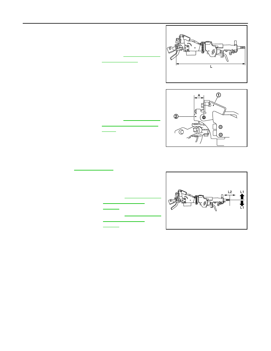
• Check tilt and telescopic mechanism operating range tilt operating
range (L1), telescopic operating range (L2) as shown in the figure.
WITH ELECTRIC MOTOR
Standard
L
: Refer to
.
JSGIA0350ZZ
Standard
A
: Refer to
JSGIA0351ZZ
Standard
L1
: Refer to
.
L2
: Refer to
.
JSGIA0345ZZ