Content .. 1751 1752 1753 1754 ..
Infiniti FX35, FX50 (S51). Manual - part 1753
ST-4
< SYMPTOM DIAGNOSIS >
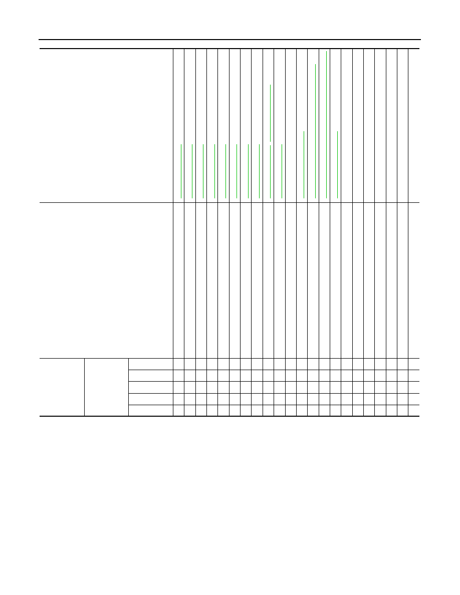
NOISE, VIBRATION AND HARSHNESS (NVH) TROUBLESHOOTING
Use the chart below to find the cause of the symptom. If necessary, repair or replace these parts.
×
: Applicable
AWD MODELS (WITHOUT ELECTRIC MOTOR)
Reference
,
—
NVH in DLN section.
NVH in DLN section.
NVH in F
A
X, RAX, FSU,
RSU section.
NVH in WT
section.
NVH in WT
section.
NVH in RAX
section.
NVH in BR section.
Possible cause and SUSPECTED PARTS
Flu
id leve
l
Ai
r in
hy
dra
u
lic
sy
st
em
Ou
te
r/in
ne
r so
ck
e
t ba
ll jo
int
s
w
in
g
in
g
t
o
rqu
e
Ou
te
r/in
ne
r so
cke
t ba
ll jo
int
rot
a
ti
ng
to
rqu
e
Ou
te
r/in
ne
r so
ck
e
t ba
ll jo
int
en
d
pla
y
S
tee
ri
ng
f
lui
d
le
a
ka
g
e
S
tee
ri
ng
wh
ee
l p
lay
S
te
e
rin
g
ge
ar ra
ck
s
lid
in
g f
o
rc
e
Dri
v
e
b
elt
lo
os
en
es
s
Imp
rop
er ste
e
ri
ng
whe
e
l
Im
pro
pe
r
in
st
al
lat
ion
o
r lo
os
en
es
s o
f t
ilt
lo
ck
l
e
ve
r
M
ou
nt
ing
lo
os
en
es
s
S
tee
ri
ng
c
o
lu
m
n
d
e
fo
rm
at
io
n
or da
ma
ge
Im
pro
pe
r
in
st
al
lat
ion
o
r lo
os
en
es
s o
f st
e
eri
ng
co
lu
mn
S
te
erin
g lin
ka
ge
lo
os
en
es
s
PROP
ELLER SHAFT
D
IFFERENTIAL
AXLE and
S
U
S
PENSION
TIRE
R
O
AD WHEEL
D
R
IVE SHAF
T
BRAKE
Symptom
Steering
Noise
× × × × × × × × ×
× ×
× × × × × × ×
Shake
×
×
×
× × × × ×
Vibration
×
× × ×
×
× ×
×
Shimmy
×
×
×
× × ×
×
Judder
×
×
× × ×
×