Content .. 1729 1730 1731 1732 ..
Infiniti FX35, FX50 (S51). Manual - part 1731
B1106, B1107, B1108, B1109, B1110, B1111 DIAGNOSIS SENSOR UNIT
SRC-89
< DTC/CIRCUIT DIAGNOSIS >
C
D
E
F
G
I
J
K
L
M
A
B
SRC
N
O
P
B1106, B1107, B1108, B1109, B1110, B1111 DIAGNOSIS SENSOR UNIT
Description
INFOID:0000000005241160
Checks the entire SRS and displays the malfunction either by illuminating or blinking the air bag warning lamp
on the combination meter. Malfunctioning part can be detected by on board self-diagnosis system and CON-
SULT-III.
OPERATION
It detects a shock that exceeds a specified level and monitors whether the driver and passenger air bags, front
side air bag, side curtain air bag and pre-tensioner seat belts operate normally.
STRUCTURE
It contains the “G” sensors for both frontal and side collisions and spare battery function in case of main bat-
tery damage in collision.
INSTALLATION
Air bag diagnosis sensor unit is installed under the center console with fixed bolts.
DTC Logic
INFOID:0000000005241161
DTC CONFIRMATION PROCEDURE
1.
CHECK SELF-DIAG RESULT
With CONSULT-III
1.
Turn ignition switch ON.
2.
Perform “AIR BAG” Self Diagnostic Result.
Without CONSULT-III
1.
Turn ignition switch ON.
2.
Check the air bag warning lamp status. Refer to
SRC-16, "Air Bag Warning Lamp Diagnosis"
.
NOTE:
SRS does not enter diagnosis mode if no malfunction is detected in user mode.
Is malfunctioning part detected?
YES
>> Refer to
NO
>> INSPECTION END
Diagnosis Procedure
INFOID:0000000005241162
WARNING:
• Before servicing, turn ignition switch OFF, disconnect battery negative terminal and wait at least 3
minutes. (To discharge backup capacitor.)
• Never use unspecified tester or other measuring device.
1.
CHECK HARNESS CONNECTOR
Check the harness connector.
Is the inspection result normal?
YES
>> GO TO 2.
NO
>> Replace harness connectors.
2.
CHECK WIRING HARNESS
Check the wiring harness externals.
Is the inspection result normal?
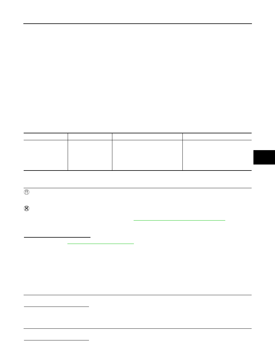
DTC No.
Trouble diagnosis name
DTC detecting condition
Possible cause
B1106
B1107
B1108
B1109
B1110
B1111
CONTROL UNIT
Air bag diagnosis sensor unit is mal-
functioning or out of the specification
• Malfunction in air bag diagnosis sen-
sor unit
• Configuration in air bag diagnosis
sensor unit does not match the vehi-
cles specification