Infiniti FX35, FX50 (S51). Manual - part 173


  Index      Infiniti     Infiniti FX35, FX50 (S51) - service repair manual 2010 year


Search            


Content   ..  171  172  173  174   ..


Infiniti FX35, FX50 (S51). Manual - part 173


AV

INSPECTION AND ADJUSTMENT

AV-465

< BASIC INSPECTION >

[NAVIGATION (TWIN MONITOR)]

C

D

E

F

G

H

I

J

K

L

M

B

A

O

P

• The adjustment value is cancelled on this mode by performing “Initialize Camera Image Calibration”. 

Is the difference corrected?

YES

>> Finish the writing to around view monitor control unit by pressing “ENTER” switch. 

NO

>> GO TO 5.

5.

PERFORM “CALIBRATING CAMERA IMAGE”

Preparation of target line
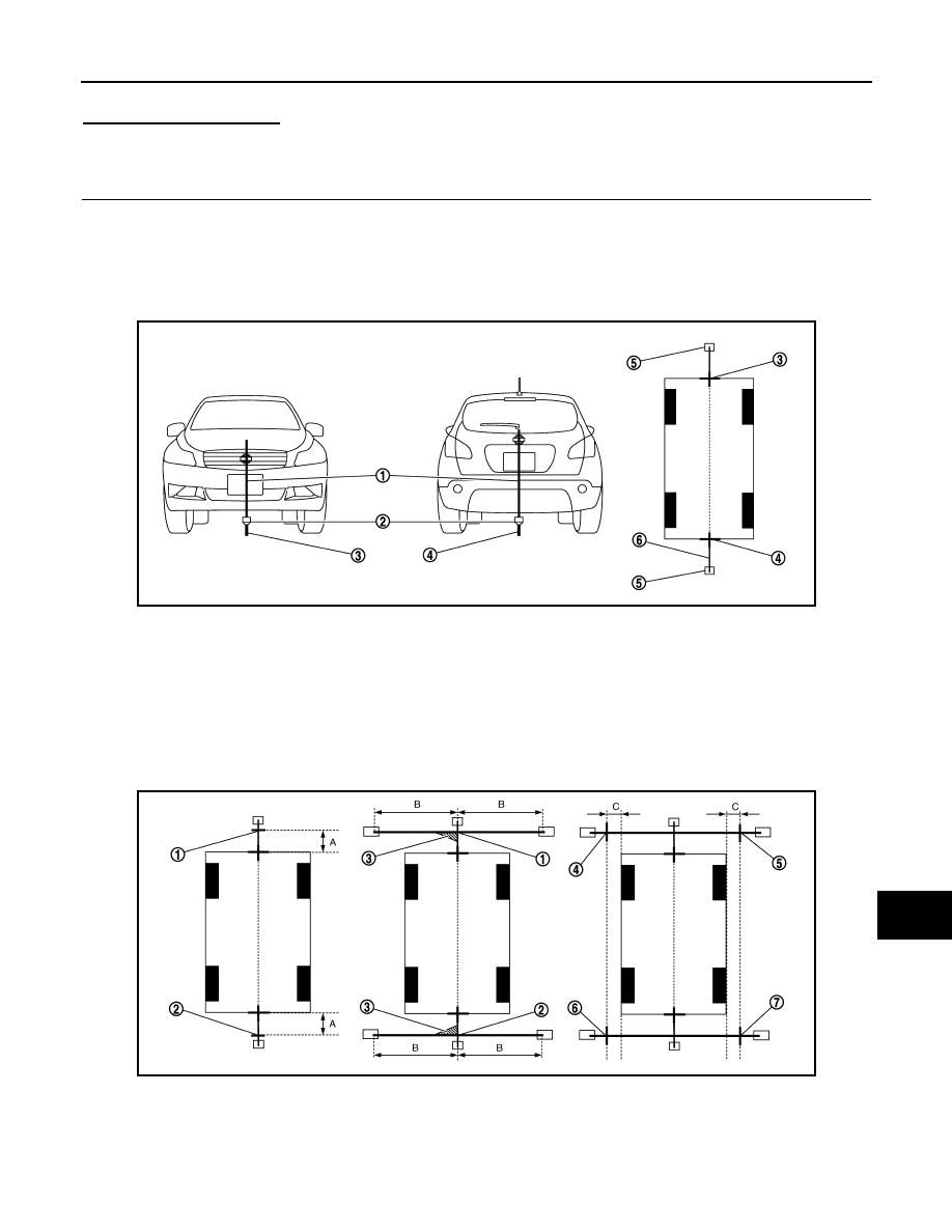
1.

Hang a string with a weight as shown in the figure. Put the points FM0, RM0 (mark) on the ground at the
center of the vehicle front end and rear end with white packing tape or a pen. 

2.

Route the vinyl string under the vehicle, and then pull and fix it on the point approximately 1.0 m (39.9 in)
to the front and rear of the vehicle through the points FM0 and RM0 using packing tape. 

Target line preparation procedure 1

3.

Put the points FM and RM (mark) 75 cm (29.5 in) from the points FM0 and RM0 individually. 

4.

Route the vinyl string through the points FM and RM using a triangle scale, and then fix it at approximately
1.5 m (59 in) on both sides with packing tape. 

5.

Put the points FL, FR, RL, and RR (mark) to both right and left [vehicle width / 2 + 30 cm (11.8 in)] from the
points FM and RM. 

Target line preparation procedure 2

JSNIA1054ZZ

1.

Thread

2.

Weight

3.

Point FM0 (mark)

4.

Point RM0 (mark)

5.

Packing tape (to fix the vinyl string)

6.

Vinyl string

JSNIA0921ZZ

1.

Point FM

2.

Point RM

3.

Triangle scale

4.

Point FL (mark)

5.

Point FR (mark)

6.

Point RL (mark)

AV-466

< BASIC INSPECTION >

[NAVIGATION (TWIN MONITOR)]

INSPECTION AND ADJUSTMENT

6.

Draw the lines of the points FL – RL and FR – RR with vinyl string, and fix it with packing tape. 

7.

Put a mark on the center of each axle, draw vertical lines to the lines of the points FL – RL and FR – RR
from the marks on the center of the axle using a triangle scale, and then fix the lines using packing tape. 

Target line preparation procedure 3

Perform “Calibrating Camera Image”
1.

Select “Camera Cont.” of “Confirmation/ Adjustment” mode, and then set to “Calibrating Camera Image”
mode. 

2.

Overlap the target lines drawn on the ground with the calibration
marker on the screen by operating the center dial and upper/
lower/left/right switches of multifunction switch on each screen
of “Rear Camera”, “Pass-Side Camera”, “Front Camera”, “Dr-
Side Camera”. 

3.

“Writing...” is displayed by pressing the “ENTER” switch, and then the adjustment result is written to the
around view monitor control unit. 

CAUTION:

Check that “Writing...” is displayed. Do never perform other operations while “Writing...” is dis-
played. 

>> GO TO 6.

6.

PERFORM “FINE TUNING OF BIRDS-EYE VIEW”

This mode is designed to align the boundary between each camera image that could not be aligned in the
“Calibrating Camera Image” mode. 
1.

Select “Camera Cont.” of “Confirmation/ Adjustment” mode, and then set to “Fine Tuning of Birds-Eye
View” mode. 

7.

Point RR (mark)

A.

75 cm (29.5 in)

B.

Approx. 1.5 m (59 in)

C.

30 cm (11.8 in)
[Vehicle width/ 2 + 30 cm (11.8 in) 
from the points FM and RM]

JSNIA0922ZZ

1.

Point FL

2.

Point FR

3.

Point RL

4.

Point RR

5.

Center position of axle

6.

Triangle scale

Adjustment range

Rotation direction (Center dial)

: 31 patterns (16 on the center)

Upper/lower direction (upper/lower 
switch)

99 – 99

Left/right direction (left/right switch)

99 – 99

JSNIA2379ZZ

AV

INSPECTION AND ADJUSTMENT

AV-467

< BASIC INSPECTION >

[NAVIGATION (TWIN MONITOR)]

C

D

E

F

G

H

I

J

K

L

M

B

A

O

P

2.

Operate the center dial and upper/lower/left/right switch to over-
lap the marker on the screen and the target lines on the ground. 
NOTE:
Move the “+”- mark on the camera position to adjustment by
pressing the “CAMERA” switch. 

3.

When the target line is overlapped on the marker, press the
“ENTER” switch to write the adjustment result to the around
view monitor control unit. 

CAUTION:

Check that “Writing...” is displayed. Do never perform other
operations while “Writing...” is displayed. 
NOTE:
• It can be initialized to the NISSAN factory default condition with “Initialize Camera Image Calibration” of

“Calibrating Camera Image”. 

• The adjustment value is cancelled on this mode by performing “Initialize Camera Image Calibration”. 

>> Calibration end

JSNIA2280ZZ

AV-468

< DTC/CIRCUIT DIAGNOSIS >

[NAVIGATION (TWIN MONITOR)]

U1000 CAN COMM CIRCUIT

DTC/CIRCUIT DIAGNOSIS

U1000 CAN COMM CIRCUIT

Description

INFOID:0000000005474768

CAN (Controller Area Network) is a serial communication line for real-time application. It is an on-vehicle mul-
tiplex communication line with high data communication speed and excellent error detection ability. Many elec-
tronic control units are equipped onto a vehicle, and each control unit shares information and links with other
control units during operation (not independently). In CAN communication, control units are connected with 2
communication lines (CAN-H, CAN-L) allowing a high rate of information transmission with less wiring. Each
control unit transmits/receives data but selectively reads required data only.
CAN Communication Signal Chart. Refer to 

LAN-30, "CAN Communication Signal Chart"

.

DTC Logic

INFOID:0000000005474769

DTC DETECTION LOGIC

Diagnosis Procedure

INFOID:0000000005474770

1.

PERFORM SELF-DIAGNOSTIC

1.

Turn ignition switch ON and wait for 2 seconds or more.

2.

Check “Self Diagnostic Result” of “MULTI AV”. 

Is “CAN COMM CIRCUIT” displayed?

YES

>> Refer to “LAN system”. Refer to 

LAN-20, "Trouble Diagnosis Procedure"

.

NO

>> Refer to GI section. Refer to 

GI-36, "Intermittent Incident"

.

DTC

Display contents of CON-

SULT-III

DTC detection condition

Probable malfunction location

U1000

CAN COMM CIRCUIT
[U1000]

AV control unit is not transmitting or receiving 
CAN communication signal for 2 seconds or 
more.

CAN communication system.


Content   ..  171  172  173  174   ..