Content .. 1631 1632 1633 1634 ..
Infiniti FX35, FX50 (S51). Manual - part 1633
SE-52
< ECU DIAGNOSIS INFORMATION >
CLIMATE CONTROLLED SEAT CONTROL UNIT
ECU DIAGNOSIS INFORMATION
CLIMATE CONTROLLED SEAT CONTROL UNIT
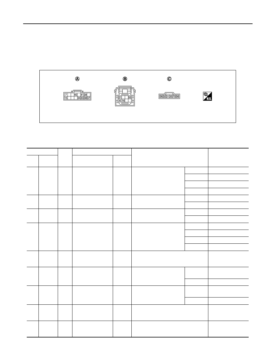
Reference Value
INFOID:0000000005236637
TERMINAL LAYOUT
PHYSICAL VALUES
A.
B507
B.
B508
C.
B509
JMJIA2080ZZ
Terminal No.
Wire
color
Description
Condition
Value
(Approx.)
+
–
Signal name
Input/
Output
6
Ground
R
COOL switch signal
Input
Climate controlled seat
switch
HI COOL
2.6 - 4.2
MID COOL
1.6 - 2.5
LO COOL
0.8 - 1.5
OFF
0
7
Ground
L
HEAT switch indicator
signal
Output
Climate controlled seat
switch
HEAT
Battery voltage
OFF
0
15
Ground
W
COOL switch indica-
tor signal
Output
Climate controlled seat
switch
COOL
Battery voltage
OFF
0
16
Ground
G
HEAT switch signal
Input
Climate controlled seat
switch
HI HEAT
2.6 - 4.2
MID HEAT
1.6 - 2.5
LO HEAT
0.8 - 1.5
OFF
0
21
Ground
P
Climate controlled
seat switch power
supply
Output
Ignition switch ON
Battery voltage
31
Ground
L/R
Seat cushion thermal
electric device HEAT
signal
Input
Climate controlled seat
switch
HEAT or
COOL
0 - Battery voltage*
OFF
0
32
Ground
G/R
Seat cushion thermal
electric device COOL-
signal
Input
Climate controlled seat
switch
HEAT or
COOL
0 - Battery voltage*
OFF
0
33
Ground
B/R
Seat cushion thermal
electric device sensor
signal
Input
Climate controlled seat operated
1 - 5
34
Ground
Y/R
Seat cushion thermal
electric device sensor
ground
—
Ignition switch ON
0