Content .. 1576 1577 1578 1579 ..
Infiniti FX35, FX50 (S51). Manual - part 1578
RSU-10
< REMOVAL AND INSTALLATION >
REAR SHOCK ABSORBER
REAR SHOCK ABSORBER
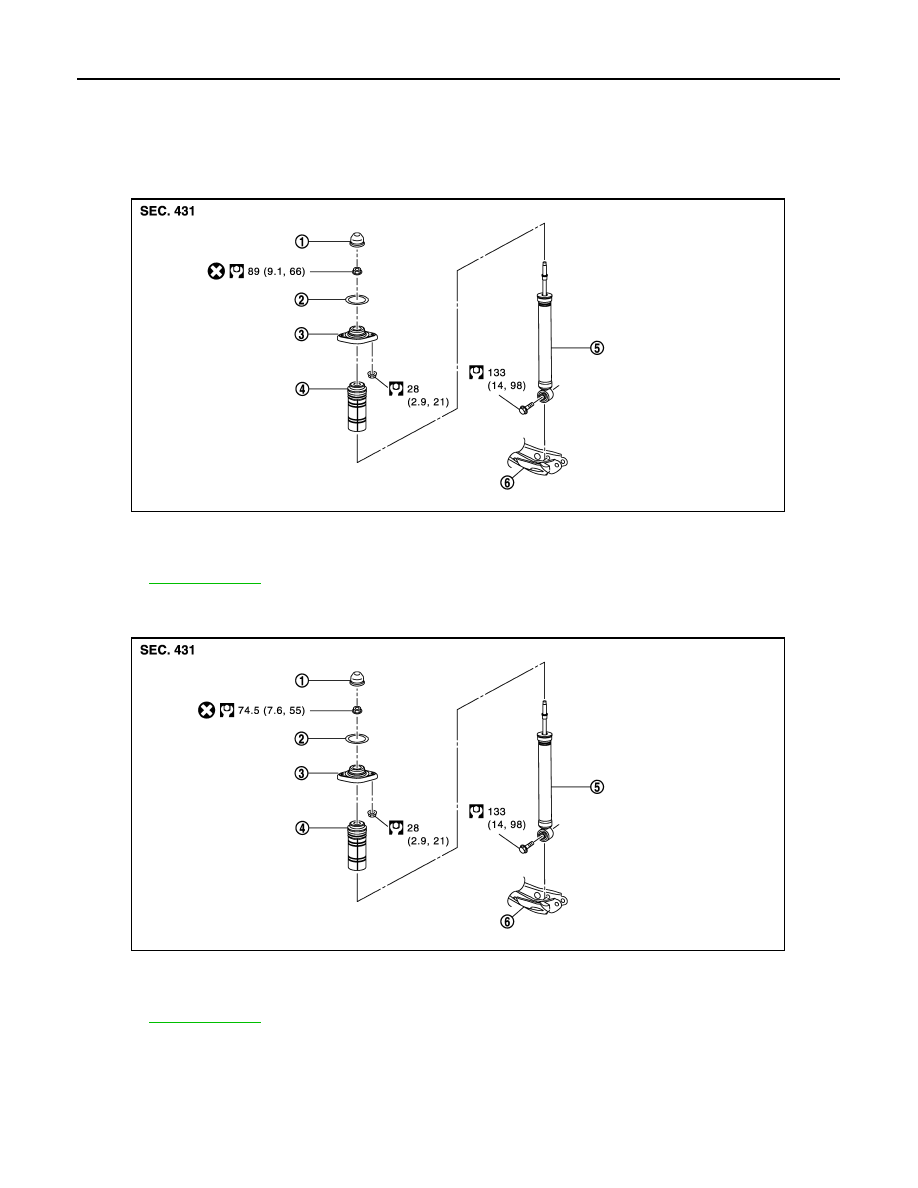
Exploded View
INFOID:0000000005249854
WITHOUT CONTINUOUS DAMPING CONTROL
WITH CONTINUOUS DAMPING CONTROL
Removal and Installation
INFOID:0000000005249855
REMOVAL
1.
Remove tires with power tool.
2.
Remove shock absorber actuator harness connector (with Continuous Damping Control).
1.
Cap
2.
Mounting seal
3.
Shock absorber mounting bracket
4.
Bound bumper cover
5.
Shock absorber
6.
Front lower link
Refer to
for symbols in the figure.
JPEIB0115GB
1.
Cap
2.
Mounting seal
3.
Shock absorber mounting bracket
4.
Bound bumper cover
5.
Shock absorber
6.
Front lower link
Refer to
for symbols in the figure.
JPEIB0130GB