Content .. 1481 1482 1483 1484 ..
Infiniti FX35, FX50 (S51). Manual - part 1483
PG
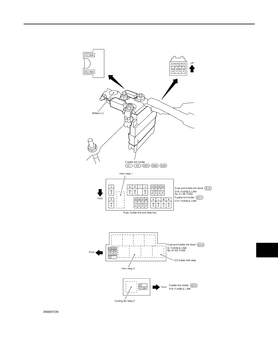
FUSE, FUSIBLE LINK AND RELAY BOX
PG-157
< DTC/CIRCUIT DIAGNOSIS >
[POWER SUPPLY & GROUND CIRCUIT]
C
D
E
F
G
H
I
J
K
L
B
A
O
P
N
FUSE, FUSIBLE LINK AND RELAY BOX
Fuse and Fusible Link Arrangement
INFOID:0000000005240772
JCMWA5128GB