Infiniti FX35, FX50 (S51). Manual - part 145
AV
REAR CAMERA
AV-353
< REMOVAL AND INSTALLATION >
[NAVIGATION (SINGLE MONITOR)]
C
D
E
F
G
H
I
J
K
L
M
B
A
O
P
REAR CAMERA
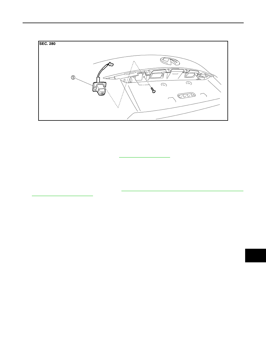
Exploded View
INFOID:0000000005475604
Removal and Installation
INFOID:0000000005475605
REMOVAL
1.
Remove door handle cover upper. Refer to
2.
Remove rear camera mounting screws and rear camera harness connector.
3.
Remove rear camera.
INSTALLATION
1.
Installation is the reverse order of removal.
2.
Perform camera image calibration. Refer to
AV-245, "CALIBRATING CAMERA IMAGE (AROUND VIEW
CAUTION:
Perform the calibration and perform the writing to the around view monitor control unit when remov-
ing and replacing each camera, removing the camera mounting parts (front grille, door mirror, etc.)
and replacing the around view monitor control unit.
JSNIA1470ZZ
1.
Rear camera