Infiniti FX35, FX50 (S51). Manual - part 1263


  Index      Infiniti     Infiniti FX35, FX50 (S51) - service repair manual 2010 year


Search            


Content   ..  1261  1262  1263  1264   ..


Infiniti FX35, FX50 (S51). Manual - part 1263


IP-20

< REMOVAL AND INSTALLATION >

INSTRUMENT PANEL ASSEMBLY

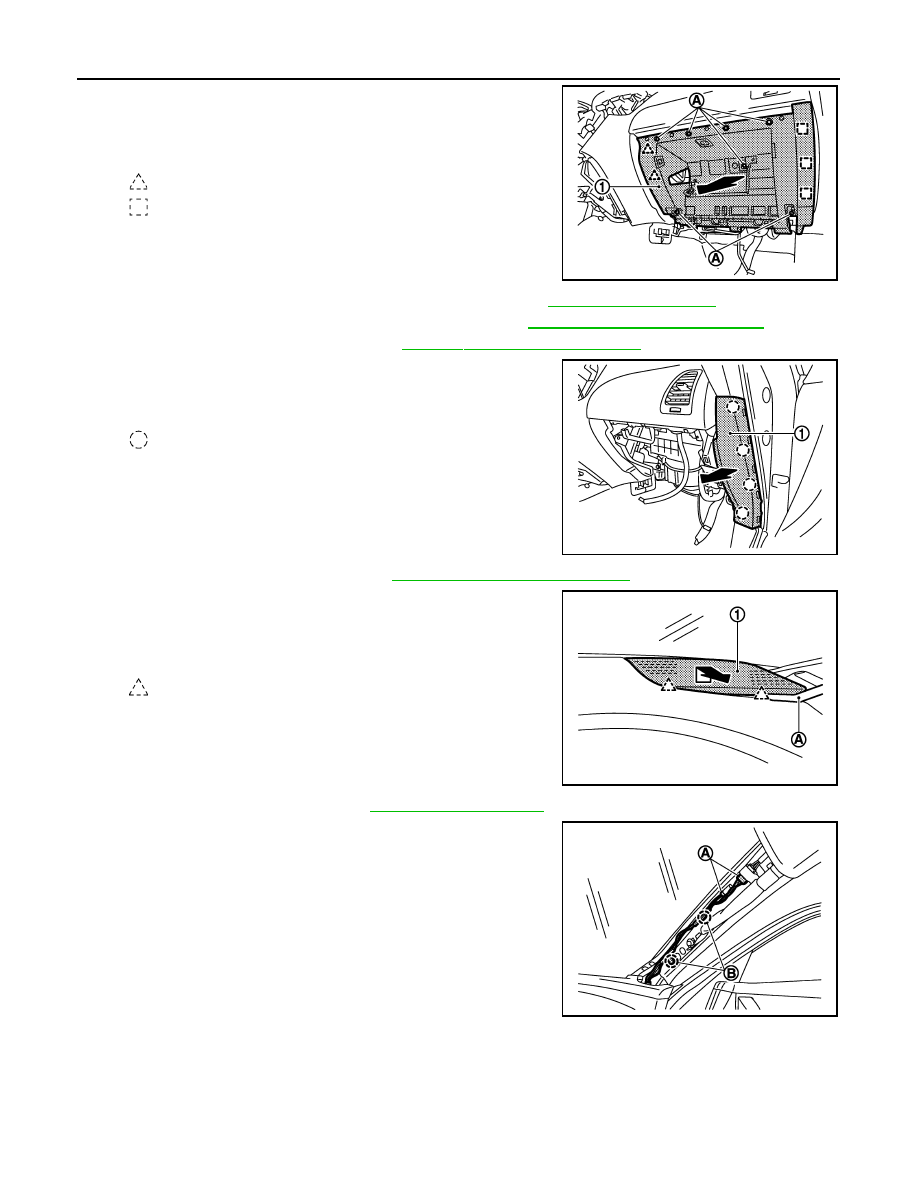
45. Remove instrument lower panel RH.

• Remove instrument lower panel RH (1) fixing screws (A).
• Pull back instrument lower panel RH.
• Disconnect glove box lamp harness connector.

46. Disconnect front passenger air bag module connector. Refer to 

SR-17, "Exploded View"

.

47. Remove front passenger air bag module fixing bolt. Refer to 

SR-17, "Removal and Installation"

.

48. Remove front body side welt RH. Refer to 

INT-17, "Removal and Installation"

.

49. Remove instrument side finisher RH.

• Insert a remover tool into lower space.
• Pull the instrument side finisher RH (1) crosswise.

50. Remove front pillar garnish RH. Refer to 

INT-17, "Removal and Installation"

.

51. Remove speaker grille RH.

• Remove speaker grille RH (1) fixing pawls with remover tool

(A).

• Pull up and back speaker grille RH (1).

52. Remove front squawker RH. Refer to 

AV-141, "Exploded View"

.

53. Disconnect antenna connectors (A).

54. Remove harness clips (B).

: Pawl

: Metal clip

JMJIA1996ZZ

: Clip

JMJIA1997ZZ

: Pawl

JMJIA1998ZZ

JMJIA1999ZZ

INSTRUMENT PANEL ASSEMBLY

IP-21

< REMOVAL AND INSTALLATION >

C

D

E

F

G

H

I

K

L

M

A

B

IP

N

O

P

55. Remove instrument panel assembly mounting bolts (A), screws (B) and clips (C).

56. Remove instrument panel assembly.

CAUTION:

• Cover center console upper surface with a shop cloth to prevent it from being damaged.
• When removing instrument panel assembly, 2 workers are required so as to prevent it from drop-

ping.

57. Remove the following parts after removing instrument panel assembly.

• Front passenger air bag module. Refer to 

SR-17, "Removal and Installation"

.

• Side ventilator grille LH/RH. Refer to 

VTL-12, "SIDE VENTILATOR GRILLE : Removal and Installation"

.

• Ventilator duct LH/RH. Refer to 

VTL-14, "VENTILATOR DUCT : Removal and Installation"

.

• Adaptor duct. Refer to 

VTL-14, "ADAPTOR DUCT : Removal and Installation"

.

• Defroster nozzle. Refer to 

VTL-15, "DEFROSTER NOZZLE : Removal and Installation"

.

• Side defroster nozzle LH/RH. Refer to 

VTL-15, "SIDE DEFROSTER NOZZLE : Removal and Installa-

tion"

.

• Antenna feeder. Refer to 

AV-156, "Feeder Layout"

.

• GPS antenna. Refer to 

AV-349, "Exploded View"

.

• Trip A/B reset switch. Refer to 

MWI-149, "Removal and Installation"

.

INSTALLATION

Install in the reverse order of removal.

JMJIA2000ZZ

IP-22

< REMOVAL AND INSTALLATION >

CENTER CONSOLE ASSEMBLY

CENTER CONSOLE ASSEMBLY

Exploded View

INFOID:0000000005241041

Removal and Installation

INFOID:0000000005241042

REMOVAL

1.

Indicator assembly

2.

Console finisher assembly

3.

Console switch finisher

4.

Console pocket assembly

5.

Socket inner case

6.

Socket knob

7.

Pocket

8.

Center console assembly

9.

Console bracket

10. Inside key antenna

11.

Socket knob

12. Socket inner case

13. Console rear finisher

14. Rear ventilator grille

15. Console lid assembly

16. Socket knob

17. Socket inner case

18. Console box assembly

19. DVD player (if equipped)

20. DVD finisher (if equipped)

21. Auxiliary input jacks

22. Cup holder assembly

23. Console upper finisher

24. Console hinge mask

25. USB connector

JMJIA2001ZZ

CENTER CONSOLE ASSEMBLY

IP-23

< REMOVAL AND INSTALLATION >

C

D

E

F

G

H

I

K

L

M

A

B

IP

N

O

P

1.

Remove selector lever knob. Refer to 

TM-169, "Removal and Installation"

.

2.

Remove console upper finisher.
• Open the console lid.
• Remove console upper finisher (1) fixing pawls with remover

tool (A).

• Pull back console upper finisher.

3.

Remove console finisher assembly.
• Remove console finisher assembly (1) fixing clips with

remover tool (A).

• Pull up console finisher assembly.
• Disconnect harness connector.

4.

Remove console switch finisher.
• Remove console switch finisher (1) fixing screws (A).
• Pull up console switch finisher.
• Disconnect harness connectors.

5.

Remove console pocket assembly.
• Pull back console pocket assembly (1), and disengage clips.
• Disconnect harness connector.

6.

Disconnect USB connector harness connector (A).

7.

Disconnect auxiliary input jacks harness connector (B).

8.

Disconnect console power socket harness connector (C).

9.

Disconnect DVD player harness connector (D).

: Pawl

JMJIA1972ZZ

: Clip

JMJIA1973ZZ

JMJIA1974ZZ

: Clip

JMJIA1975ZZ

JMJIA1976ZZ


Content   ..  1261  1262  1263  1264   ..