Infiniti FX35, FX50 (S51). Manual - part 1168


  Index      Infiniti     Infiniti FX35, FX50 (S51) - service repair manual 2010 year


Search            


Content   ..  1166  1167  1168  1169   ..


Infiniti FX35, FX50 (S51). Manual - part 1168


UNIFIED METER AND A/C AMP.

HAC-69

< DTC/CIRCUIT DIAGNOSIS >

[AUTOMATIC AIR CONDITIONER]

C

D

E

F

G

H

J

K

L

M

A

B

HAC

N

O

P

UNIFIED METER AND A/C AMP.

Description

INFOID:0000000005246248

COMPONENT DESCRIPTION

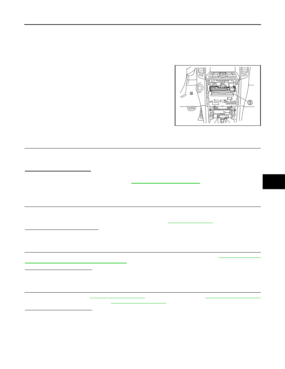
Unified Meter and A/C Amp. (Automatic Amplifier)

The unified meter and A/C amp. (1) has a built-in microcomputer
which processes information sent from various sensors needed for
air conditioner operation. The air mix door motors, mode door motor,
intake door motor, blower motor and compressor are then controlled.
When the various switches and temperature control dial are oper-
ated, data is input to the unified meter and A/C amp. from the AV
control unit using CAN communication.
Self-diagnosis functions are also built into unified meter and A/C
amp. to provide quick check of malfunctions in the auto air condi-
tioner system.

Component Function Check

INFOID:0000000005246249

1.

CONFIRM SYMPTOM BY PERFORMING THE FOLLOWING OPERATIONAL CHECK

1.

Press AUTO switch.

2.

Display should indicate AUTO. Confirm that the compressor clutch engages (sound or visual inspection).
(Discharge air and blower speed depend on ambient, in-vehicle and set temperatures.)

Does magnet clutch engaged?

YES

>> INSPECTION END

NO

>> Go to Diagnosis Procedure. Refer to 

HAC-69, "Diagnosis Procedure"

.

Diagnosis Procedure

INFOID:0000000005246250

1.

INSPECTION BY FAIL-SAFE FUNCTION

1.

Turn the ignition switch ON.

2.

After approximately 30 seconds, check that the air conditioner is operated by the fail-safe function (the
operation display of air conditioner is not performed). Refer to 

HAC-152, "Fail-safe"

.

Is the fail-safe function operated? 

YES

>> GO TO 3.

NO

>> GO TO 2.

2.

CHECK UNIFIED METER AND A/C AMP. POWER SUPPLY CIRCUIT AND GROUND

Check unified meter and A/C amp. power supply circuit and ground circuit. Refer to 

HAC-68, "UNIFIED

METER AND A/C AMP. : Diagnosis Procedure"

.

Is the inspection result normal?

YES

>> GO TO 3.

NO

>> Repair or replace parts according to the inspection results.

3.

CHECK PRESET SWITCH

Check preset switch. Refer to 

AV-130, "Symptom Table"

 (WITHOUT NAVIGATION), 

AV-321, "Symptom Table"

[NAVIGATION (SINGLE MONITOR)] or 

AV-549, "Symptom Table"

 [NAVIGATION (TWIN MONITOR)].

Is the inspection result normal?

YES

>> Replace unified meter and A/C amp.

NO

>> Repair or replace malfunctioning part(s).

JSIIA1290ZZ

HAC-70

< DTC/CIRCUIT DIAGNOSIS >

[AUTOMATIC AIR CONDITIONER]

MODE DOOR MOTOR

MODE DOOR MOTOR

Description

INFOID:0000000005246251

COMPONENT DESCRIPTION

Mode Door Motor

The mode door motor (1) are attached to the heater & cooling unit
assembly. It rotates so that air is discharged from the outlet set by
the unified meter and A/C amp. Motor rotation is conveyed to a link
which activates the mode door.

Component Function Check

INFOID:0000000005246252

1.

CONFIRM SYMPTOM BY PERFORMING THE FOLLOWING OPERATIONAL CHECK

1.

Press MODE switch and DEF switch.

2.

Each position indicator should change shape.

3.

Confirm that discharge air comes out according to the air distribution table at below. Refer to 

HAC-24,

"WITHOUT ACCS : System Description"

 (WITHOUT ACCS) or 

HAC-33, "WITH ACCS : System Descrip-

tion"

 (WITH ACCS).

NOTE:
Confirm that the compressor clutch is engaged (Sound or visual inspection) and intake door position is at FRE
when DEF 

 or D/F 

 is selected.

Is the inspection result normal?

YES

>> INSPECTION END

NO

>> Go to diagnosis procedure. Refer to 

HAC-70, "Diagnosis Procedure"

.

Diagnosis Procedure

INFOID:0000000005246253

1.

PERFORM SELF-DIAGNOSIS

Perform self-diagnosis function. Refer to 

HAC-57, "WITHOUT ACCS : Diagnosis Description"

 (WITHOUT

ACCS) or 

HAC-62, "WITH ACCS : Diagnosis Description"

 (WITH ACCS).

Is the inspection result normal?

YES

>> GO TO 5.

NO

>> GO TO 2.

2.

CHECK POWER SUPPLY FOR MODE DOOR MOTOR

Check voltage between mode door motor harness connector and ground.

Is the inspection result normal?

YES

>> GO TO 3.

NO

>> Repair harness or connector.

3.

CHECK SIGNAL FOR MODE DOOR MOTOR

Confirm A/C LAN signal between mode door motor harness connector and ground using an oscilloscope.

:

Vehicle front

JSIIA0005GB

(+)

(

)

Voltage

(Approx.)

Mode door motor

Connector

Terminal

M253

1

Ground

12 V

MODE DOOR MOTOR

HAC-71

< DTC/CIRCUIT DIAGNOSIS >

[AUTOMATIC AIR CONDITIONER]

C

D

E

F

G

H

J

K

L

M

A

B

HAC

N

O

P

Is the inspection result normal?

YES

>> GO TO 4.

NO

>> Repair harness or connector.

4.

CHECK MODE DOOR MOTOR GROUND CIRCUIT

1.

Turn ignition switch OFF.

2.

Disconnect mode door motor connector.

3.

Check continuity between mode door motor harness connector and ground.

Is the inspection result normal?

YES

>> Replace mode door motor.

NO

>> Repair harness or connector.

5.

CHECK MODE DOOR CONTROL LINKAGE

Check mode door control linkage is properly installed. Refer to 

HAC-187, "Exploded View"

.

Is it installed normally?

YES

>> INSPECTION END

NO

>> Repair or adjust control linkage.

(+)

(

)

Voltage

Mode door motor

Connector

Terminal

M253

3

Ground

SJIA1453J

Mode door motor

Continuity

Connector

Terminal

M253

2

Ground

Existed

HAC-72

< DTC/CIRCUIT DIAGNOSIS >

[AUTOMATIC AIR CONDITIONER]

AIR MIX DOOR MOTOR (DRIVER SIDE)

AIR MIX DOOR MOTOR (DRIVER SIDE)

Description

INFOID:0000000005246254

COMPONENT DESCRIPTION

Air Mix Door Motor

The air mix door motor (driver side) (1) is attached to the heater &
cooling unit assembly. It rotates so that the air mix door is opened or
closed to a position set by the unified meter and A/C amp. Motor
rotation is then conveyed through a shaft and the air mix door posi-
tion feedback is then sent to the unified meter and A/C amp. by PBR
built-in air mix door motor.

Component Function Check

INFOID:0000000005246255

1.

CONFIRM SYMPTOM BY PERFORMING THE FOLLOWING OPERATIONAL CHECK

1.

Turn temperature control dial (driver side) clockwise until 32.0

°

C (90

°

F) is displayed.

2.

Check for warm air at discharge air outlets.

3.

Turn temperature control dial (driver side) counterclockwise until 18.0

°

C (60

°

F) is displayed.

4.

Check for cool air at discharge air outlets.

Is the inspection result normal?

YES

>> INSPECTION END

NO

>> Go to diagnosis procedure. Refer to 

HAC-72, "Diagnosis Procedure"

.

Diagnosis Procedure

INFOID:0000000005246256

1.

PERFORM SELF-DIAGNOSIS

Perform self-diagnosis function. Refer to 

HAC-57, "WITHOUT ACCS : Diagnosis Description"

 (WITHOUT

ACCS) or 

HAC-62, "WITH ACCS : Diagnosis Description"

 (WITH ACCS).

Is the inspection result normal?

YES

>> GO TO 5.

NO

>> GO TO 2.

2.

CHECK POWER SUPPLY FOR AIR MIX DOOR MOTOR (DRIVER SIDE)

Check voltage between air mix door motor (driver side) harness connector and ground.

Is the inspection result normal?

YES

>> GO TO 3.

NO

>> Repair harness or connector.

3.

CHECK SIGNAL FOR AIR MIX DOOR MOTOR (DRIVER SIDE)

Confirm A/C LAN signal between air mix door motor (driver side) harness connector and ground using an
oscilloscope.

:

Vehicle front

JSIIA1370ZZ

(+)

(

)

Voltage

(Approx.)

Air mix door motor (driver side)

Connector

Terminal

M252

1

Ground

12 V


Content   ..  1166  1167  1168  1169   ..