Infiniti FX35, FX50 (S51). Manual - part 1160


  Index      Infiniti     Infiniti FX35, FX50 (S51) - service repair manual 2010 year


Search            


Content   ..  1158  1159  1160  1161   ..


Infiniti FX35, FX50 (S51). Manual - part 1160


AUTOMATIC AIR CONDITIONER SYSTEM

HAC-37

< SYSTEM DESCRIPTION >

[AUTOMATIC AIR CONDITIONER]

C

D

E

F

G

H

J

K

L

M

A

B

HAC

N

O

P

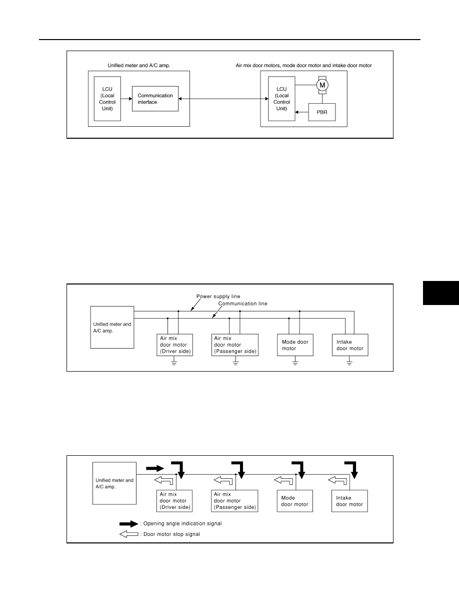
A configuration of these components is as shown in the figure below.

SYSTEM CONSTRUCTION

A small network is constructed between the unified meter and A/C amp., mode door motor, air mix door
motors and intake door motor. The unified meter and A/C amp. and motors are connected by data transmis-
sion lines and motor power supply lines. The LAN network is built through the ground circuits of each door
motor.
Addresses, motor opening angle signals, motor stop signals and error checking messages are all transmitted
through the data transmission lines connecting the unified meter and A/C amp. and each door motor.
The following functions are contained in LCUs built into the mode door motor, the air mix door motors and the
intake door motor.
• Address
• Motor opening angle signals
• Data transmission
• Motor stop and drive decision
• Opening angle sensor (PBR function)
• Comparison
• Decision (Unified meter and A/C amp. indicated value and motor opening angle comparison)

Operation

The unified meter and A/C amp. receives data from each of the sensors. The unified meter and A/C amp.
sends mode door, air mix door and intake door opening angle data to the mode door motor LCU, air mix door
motor LCUs and intake door motor LCU.
The mode door motor, air mix door motors and intake door motor read their respective signals according to the
address signal. Opening angle indication signals received from the unified meter and A/C amp. and each of
the motor position sensors is compared by the LCUs in each door motor with the existing decision and open-
ing angles. Subsequently, HOT/COLD, DEF/VENT and FRE/REC operation is selected. The new selection
data is returned to the unified meter and A/C amp.

Transmission Data and Transmission Order

Unified meter and A/C amp. data is transmitted consecutively to each of the doors motor following the form as
shown in the figure below.

JSIIA0769GB

RJIA1747E

RJIA1748E

HAC-38

< SYSTEM DESCRIPTION >

[AUTOMATIC AIR CONDITIONER]

AUTOMATIC AIR CONDITIONER SYSTEM

START:

• Initial compulsory signal is sent to each of the door motors.

ADDRESS:

• Data sent from the unified meter and A/C amp. are selected according to data-based decisions made by the

mode door motor, air mix door motors and intake door motor.

• If the addresses are identical, the opening angle data and error check signals are received by the door motor

LCUs. The LCUs then make the appropriate error decision. If the opening angle data have no error, door
control begins.

• If an error exists, the received data are rejected and corrected data received. Finally, door control is based

upon the corrected opening angle data.

OPENING ANGLE:

• Data that shows the indicated door opening angle of each door motor.

ERROR CHECK:

• In this procedure, transmitted and received data is checked for errors. Error data are then compiled. The

error check prevents corrupted data from being used by the mode door motor, the air mix door motors and
the intake door motor. Error data can be related to the following symptoms.

- Malfunction of electrical frequency
- Poor electrical connections
- Signal leakage from transmission lines
- Signal level fluctuation

STOP SIGNAL:

• At the end of each transmission, a stop operation, in-operation, or internal malfunction message is delivered

to the unified meter and A/C amp. This completes one data transmission and control cycle.

WITH ACCS : Component Part Location

INFOID:0000000005246224

ENGINE COMPARTMENT

RJIA1749E

AUTOMATIC AIR CONDITIONER SYSTEM

HAC-39

< SYSTEM DESCRIPTION >

[AUTOMATIC AIR CONDITIONER]

C

D

E

F

G

H

J

K

L

M

A

B

HAC

N

O

P

PASSENGER COMPARTMENT

1.

Gas sensor

2.

Refrigerant pressure sensor

3.

Ambient sensor

4.

Compressor (magnet clutch)

5.

Compressor (ECV)

JSIIA1292ZZ

HAC-40

< SYSTEM DESCRIPTION >

[AUTOMATIC AIR CONDITIONER]

AUTOMATIC AIR CONDITIONER SYSTEM

WITH ACCS : Component Description

INFOID:0000000005246225

1.

Intake door motor

2.

Air mix door motor (passenger side)

3.

Mode door motor

4.

Air mix door motor (driver side)

5.

Sunload sensor

6.

In-vehicle sensor

7.

Unified meter and A/C amp.

8.

Intake sensor

9.

Blower motor

JSIIA1285ZZ


Content   ..  1158  1159  1160  1161   ..