Content .. 1156 1157 1158 1159 ..
Infiniti FX35, FX50 (S51). Manual - part 1158
AUTOMATIC AIR CONDITIONER SYSTEM
HAC-29
< SYSTEM DESCRIPTION >
[AUTOMATIC AIR CONDITIONER]
C
D
E
F
G
H
J
K
L
M
A
B
HAC
N
O
P
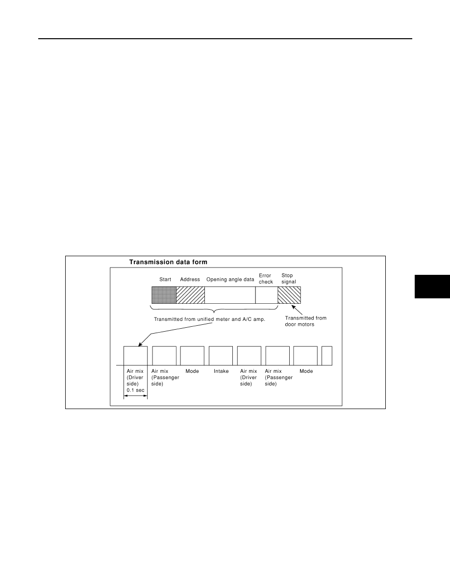
START:
• Initial compulsory signal is sent to each of the door motors.
ADDRESS:
• Data sent from the unified meter and A/C amp. are selected according to data-based decisions made by the
mode door motor, air mix door motors and intake door motor.
• If the addresses are identical, the opening angle data and error check signals are received by the door motor
LCUs. The LCUs then make the appropriate error decision. If the opening angle data have no error, door
control begins.
• If an error exists, the received data are rejected and corrected data received. Finally, door control is based
upon the corrected opening angle data.
OPENING ANGLE:
• Data that shows the indicated door opening angle of each door motor.
ERROR CHECK:
• In this procedure, transmitted and received data is checked for errors. Error data are then compiled. The
error check prevents corrupted data from being used by the mode door motor, the air mix door motors and
the intake door motor. Error data can be related to the following symptoms.
- Malfunction of electrical frequency
- Poor electrical connections
- Signal leakage from transmission lines
- Signal level fluctuation
STOP SIGNAL:
• At the end of each transmission, a stop operation, in-operation, or internal malfunction message is delivered
to the unified meter and A/C amp. This completes one data transmission and control cycle.
WITHOUT ACCS : Component Part Location
INFOID:0000000005246220
ENGINE COMPARTMENT
RJIA1749E