Content .. 1155 1156 1157 1158 ..
Infiniti FX35, FX50 (S51). Manual - part 1157
AUTOMATIC AIR CONDITIONER SYSTEM
HAC-25
< SYSTEM DESCRIPTION >
[AUTOMATIC AIR CONDITIONER]
C
D
E
F
G
H
J
K
L
M
A
B
HAC
N
O
P
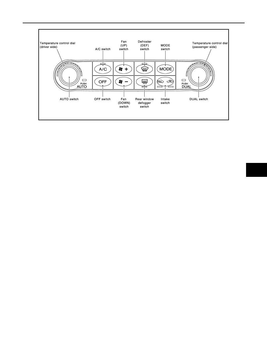
Preset Switch
MODE Switch
The air discharge outlets is controlled with this switch.
Temperature Control Dial (Potentio Temperature Control) (Driver Side)
The set temperature is increased or decreased with this dial.
Temperature Control Dial (Potentio Temperature Control) (Passenger Side)
• The set temperature is increased or decreased with this dial.
• When the temperature control dial is turned, DUAL switch indicator turns ON.
AUTO Switch
• The compressor, intake doors, air mix doors, mode doors and blower speed are automatically controlled so
that the in-vehicle temperature will reach, and be maintained at the set temperature selected by the operator.
• When pressing AUTO switch, air inlet, air outlet, fan speed, and discharge air temperature are automatically
controlled.
Defroster (DEF) Switch
Mode doors are set to the defrost position with this switch. Also, intake doors are set to the outside air position,
and compressor turns ON.
A/C Switch
Compressor is ON or OFF with this switch.
(Pressing the A/C switch when the A/C switch is ON turns OFF the A/C switch and compressor.)
FAN Switches
The blower speed is manually controlled with this switch. Seven speeds are available for manual control (as
shown on the display screen).
OFF Switch
Compressor and blower are OFF, air inlet is set to FRE, and mode position is set to foot position.
Rear Window Defogger Switch
When indicator is ON, rear window is defogged.
Intake Switch
• When intake switch is ON, FRE indicator turns ON, and air inlet is fixed to FRE.
• When intake switch is pressed again, REC indicator turns ON, and air inlet is fixed to REC.
• When intake switch is pressed for approximately 1.5 seconds or longer, FRE and REC indicators blink twice.
Then, automatic control mode is entered. Inlet status is displayed by indicator even during automatic con-
trolled.
• When FRE indicator is turned ON, shifting mode position to D/F or DEF, or when compressor is turned from
ON to OFF, intake switch is automatically turned OFF (fixed to FRE mode). REC mode can be re-entered by
pressing intake switch again, and then compressor is turned ON. (Except D/F or DEF position)
DUAL Switch
JSIIA1070GB