Content .. 1147 1148 1149 1150 ..
Infiniti FX35, FX50 (S51). Manual - part 1149
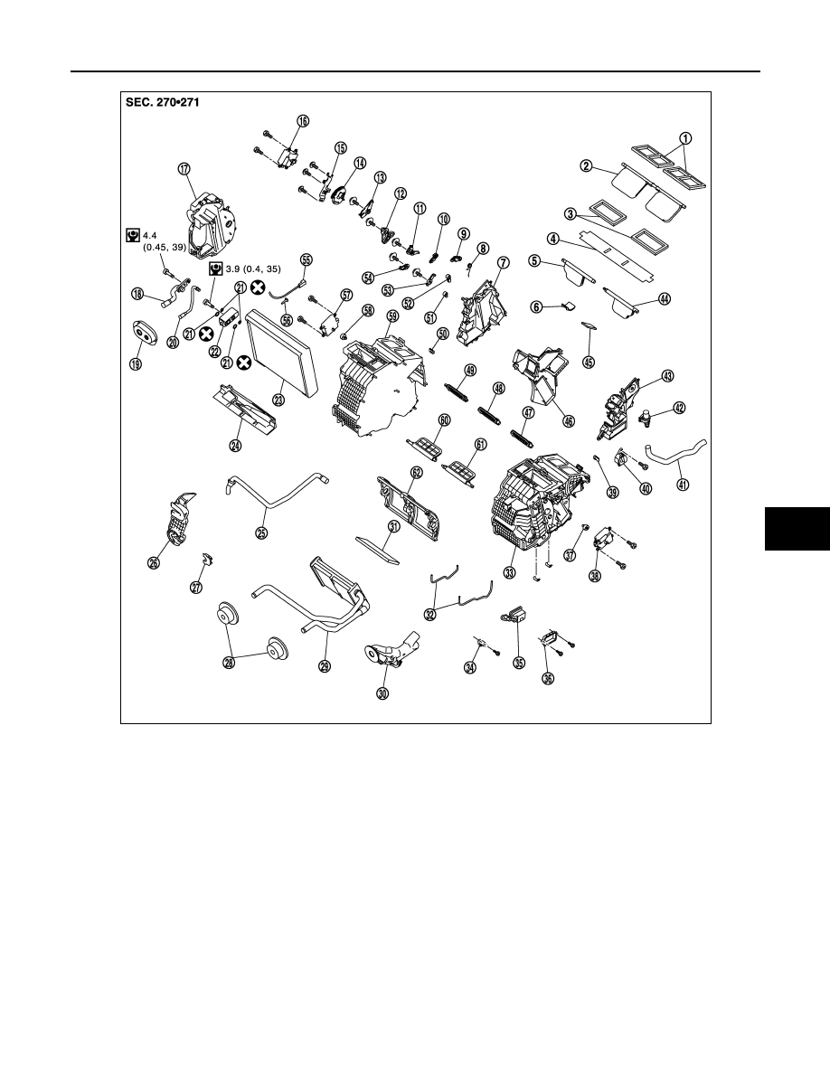
HEATER & COOLING UNIT ASSEMBLY
HA-109
< REMOVAL AND INSTALLATION >
[VK50VE]
C
D
E
F
G
H
J
K
L
M
A
B
HA
N
O
P
1.
Ventilator seal
2.
Ventilator door
3.
Defroster seal
4.
Packing
5.
Defroster door (right)
6.
Packing
7.
Foot duct (right)
8.
Ventilator door spring
9.
Ventilator door lever
10.
Foot door lever
11.
Foot door link
12. Main link sub
13.
Ventilator door link
14.
Main link
15. Mode door motor bracket
16.
Mode door motor
17.
Evaporator cover
18. Low-pressure pipe 1
19.
Cooler pipe grommet
20.
High-pressure pipe 2
21. O-ring
22.
Expansion valve
23.
Evaporator
24. Insulator
25.
Drain hose
26.
Evaporator cover adapter
27. Heater pipe bracket
28.
Heater pipe grommet
29.
Heater core
30. Heater pipe cover
31.
Packing
32.
Case packing
33. Heater & cooling unit case (left)
34.
Ionizer harness bracket
35.
Ionizer
36. Ionizer bracket
37.
Air mix door adapter
38.
Air mix door motor (driver side)
39. J-nut
40.
Front heater duct
41.
Aspirator hose
42. Aspirator
43.
Foot duct (left)
44.
Defroster door (left)
45. Packing
46.
Center case
47.
Foot door (left)
48. Rear ventilator door
JSIIA1602GB