Infiniti FX35, FX50 (S51). Manual - part 1131


  Index      Infiniti     Infiniti FX35, FX50 (S51) - service repair manual 2010 year


Search            


Content   ..  1129  1130  1131  1132   ..


Infiniti FX35, FX50 (S51). Manual - part 1131


ELECTRICAL LEAK DETECTOR

HA-37

< PERIODIC MAINTENANCE >

[VQ35HR]

C

D

E

F

G

H

J

K

L

M

A

B

HA

N

O

P

c.

Intake door position: Recirculation

d.

Temperature setting: Max. cold

e.

Fan speed: High

9.

Run engine at 1,500 rpm for at least 2 minutes.

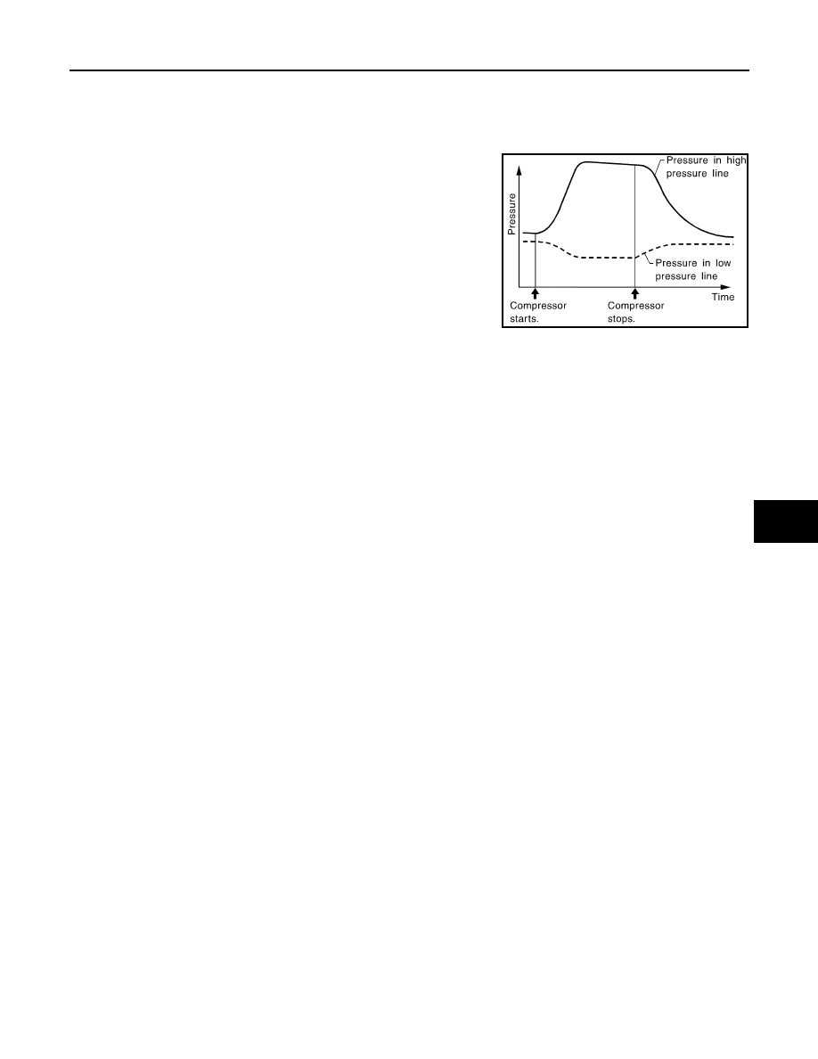
10. Stop the engine and perform leakage check again, steps 4 – 6.

Refrigerant leakages should be checked immediately after stop-
ping the engine. Begin with the leak detector at the compressor.
The pressure on the high-pressure side drops gradually after
refrigerant circulation stops and pressure on the low-pressure
side rises gradually, as shown in the graph. Some leakages are
more easily detected when pressure is high.

11. Check recovery/recycling recharging equipment gauges before connecting recovery/recycling recharging

equipment to vehicle. No refrigerant pressure should be displayed. Recover refrigerant from equipment
lines if pressure is displayed, and then check refrigerant purity.

12. Confirm refrigerant purity in supply tank using recovery/recycling recharging equipment and refrigerant

identifier.

13. Confirm refrigerant purity in vehicle A/C system using recovery/recycling recharging equipment and refrig-

erant identifier.

14. Discharge A/C system using approved refrigerant recovery equipment. Repair the leaking fitting or com-

ponent if necessary.

15. Evacuate and recharge A/C system and perform the leakage test to confirm no refrigerant leakages.

16. Perform A/C performance test to ensure system works normally.

SHA839E

HA-38

< REMOVAL AND INSTALLATION >

[VQ35HR]

COMPRESSOR

REMOVAL AND INSTALLATION

COMPRESSOR

Exploded View

INFOID:0000000005249905

Removal and Installation

INFOID:0000000005249906

REMOVAL

1.

Use a refrigerant collecting equipment (for HFC-134a) to discharge the refrigerant.

2.

Remove air cleaner case (bank 2). Refer to 

EM-29, "Exploded View"

.

3.

Remove drive belt. Refer to 

EM-15, "Removal and Installation"

.

4.

Remove mounting nuts (A), and then disconnect low-pressure
flexible hose (1) and high-pressure flexible hose (2) from com-
pressor.

CAUTION:

Cap or wrap the joint of the A/C piping and compressor with
suitable material such as vinyl tape to avoid the entry of air.

5.

Disconnect compressor (ECV) connector (A).

6.

Disconnect compressor (magnet clutch) connector (B).

7.

Remove harness clip (C)

1.

Compressor

Refer to 

GI-4, "Components"

 for symbols in the figure.

JSIIA1217GB

JSIIA1218ZZ

JSIIA1219ZZ

COMPRESSOR

HA-39

< REMOVAL AND INSTALLATION >

[VQ35HR]

C

D

E

F

G

H

J

K

L

M

A

B

HA

N

O

P

8.

Remove mounting bolts (A) from compressor (1), using power
tools.

9.

Remove compressor from the upper side of the vehicle.

10. Remove mounting bolt (A), and then remove harness bracket

(1) from compressor (2).

INSTALLATION

Installation is basically the reverse order of removal.

CAUTION:

• Replace O-rings with new ones. Then apply compressor oil to them when installing.
• Check for leakages when recharging refrigerant.
• Check tension of the drive belt after installing compressor. Refer to 

EM-15, "Checking"

.

Inspection

INFOID:0000000005249907

CHECK DISC TO PULLEY CLEARANCE

Check the clearance (B) between pulley assembly (1) and clutch
disc (2) along the entire periphery with a feeler gauge (A).

Replace compressor if specified clearance is not obtained.

JSIIA1220ZZ

JSIIA1221ZZ

Clearance

: Refer to 

HA-59, "Compressor"

.

SJIA1918E

HA-40

< REMOVAL AND INSTALLATION >

[VQ35HR]

COOLER PIPE AND HOSE

COOLER PIPE AND HOSE

Exploded View

INFOID:0000000005249908

Refer to 

HA-13, "Refrigerant Connection"

.

LOW-PRESSURE FLEXIBLE HOSE

LOW-PRESSURE FLEXIBLE HOSE : Removal and Installation

INFOID:0000000005249909

REMOVAL

1.

Use a refrigerant collecting equipment (for HFC-134a) to discharge the refrigerant.

2.

Remove air cleaner case (bank 2). Refer to 

EM-29, "Exploded View"

.

1.

O-ring

2.

Low-pressure pipe 2

3.

Low-pressure flexible hose

4.

Compressor

5.

Condenser

6.

High-pressure flexible hose

7.

High-pressure pipe 1

8.

Heater & cooling unit assembly

9.

Evaporator

10. Expansion valve

11.

High-pressure pipe 2

12. Low-pressure pipe 1

Refer to 

GI-4, "Components"

 for symbols in the figure.

JSIIA1229GB


Content   ..  1129  1130  1131  1132   ..