Infiniti FX35, FX50 (S51). Manual - part 107
AV
AV CONTROL UNIT
AV-201
< ECU DIAGNOSIS INFORMATION >
[NAVIGATION (SINGLE MONITOR)]
C
D
E
F
G
H
I
J
K
L
M
B
A
O
P
U1310
CONTROL UNIT (AV) [U1310]
U1300
U1240
• AV COMM CIRCUIT [U1300]
• SWITCH CONN [U1240]
U1300
U125B
• AV COMM CIRCUIT [U1300]
• AROUND CAMERA CONN [U125B]
U1300
U125C
• AV COMM CIRCUIT [U1300]
• SONAR CONN [U125C]
U1300
U1240
U125B
• AV COMM CIRCUIT [U1300]
• SWITCH CONN [U1240]
• AROUND CAMERA CONN [U125B]
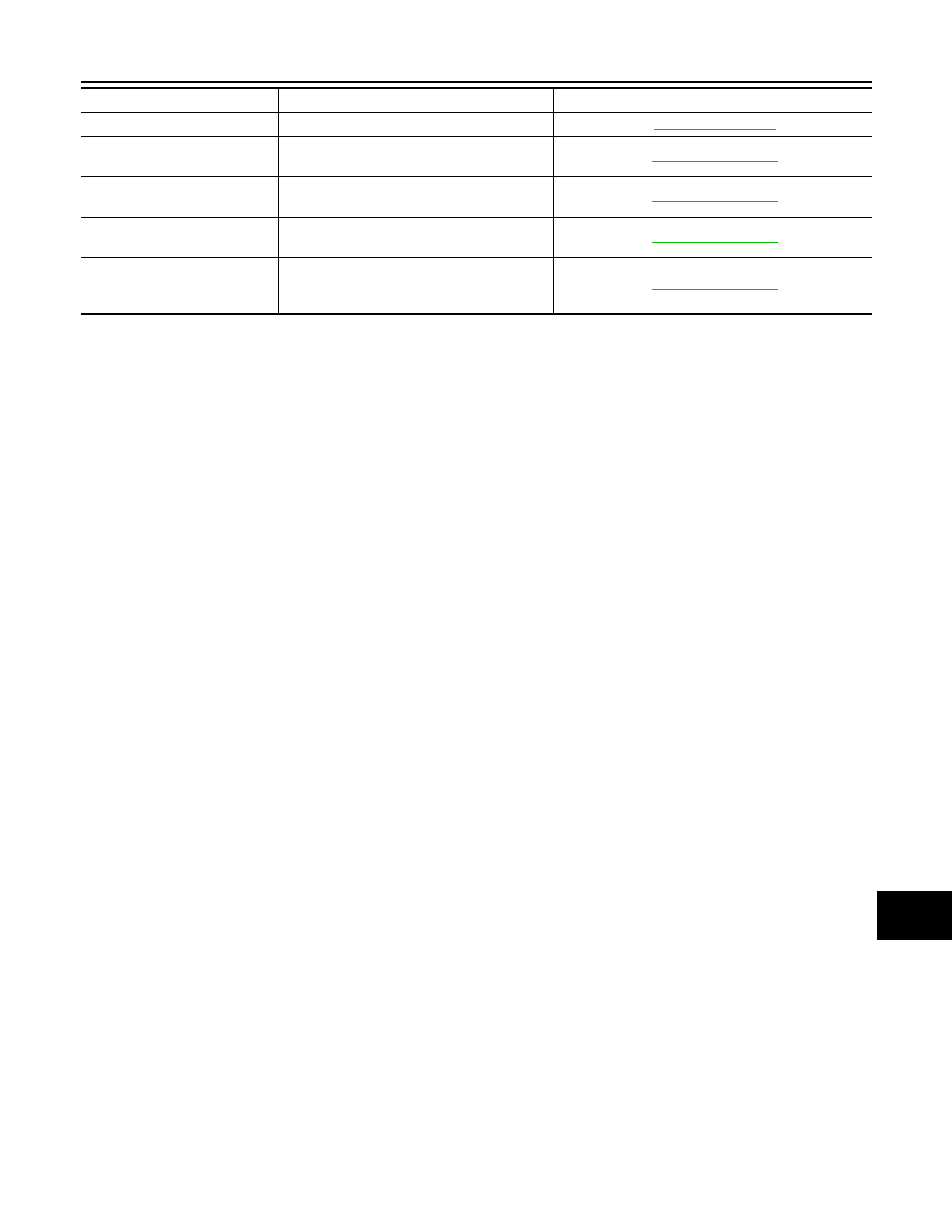
DTC
Display item
Refer to