Content .. 1015 1016 1017 1018 ..
Infiniti FX35, FX50 (S51). Manual - part 1017
EXL-64
< DTC/CIRCUIT DIAGNOSIS >
[XENON TYPE]
POWER SUPPLY AND GROUND CIRCUIT
Is the fuse fusing?
YES
>> Replace the blown fuse or fusible link after repairing the affected circuit if a fuse or fusible link is
blown.
NO
>> GO TO 2.
2.
CHECK POWER SUPPLY CIRCUIT
1.
Turn the ignition switch OFF.
2.
Disconnect IPDM E/R connector.
3.
Check voltage between IPDM E/R harness connector and ground.
Is the measurement value normal?
YES
>> GO TO 3.
NO
>> Repair harness or connector.
3.
CHECK GROUND CIRCUIT
Check continuity between IPDM E/R harness connectors and ground.
Does continuity exist?
YES
>> INSPECTION END
NO
>> Repair harness or connector.
AFS CONTROL UNIT
AFS CONTROL UNIT : Diagnosis Procedure
INFOID:0000000005244727
1.
FUSE INSPECTION
Check that the following fuses are not fusing.
Is the fuse fusing?
YES
>> Repair the applicable circuit. And then replace the fuse.
NO
>> GO TO 2.
2.
CHECK POWER SUPPLY CIRCUIT
1.
Turn the ignition switch OFF.
2.
Disconnect AFS control unit harness connector.
3.
Turn the ignition switch ON.
4.
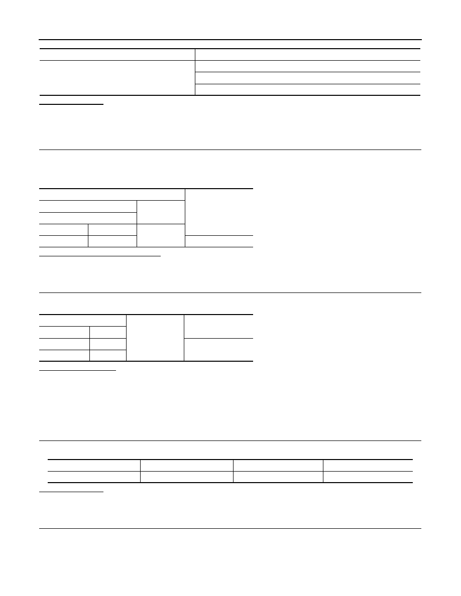
Check voltage between the AFS control unit harness connector and the ground.
Signal name
Fuses and fusible link No.
Battery power supply
D
50
51
Terminals
Voltage
(Approx.)
(+)
(
−
)
IPDM E/R
Connector
Terminal
Ground
E4
1
Battery voltage
IPDM E/R
Ground
Continuity
Connector
Terminal
E5
12
Existed
E6
41
Signal name
Connection position
Fuse No.
Capacity
Ignition power supply
FUSE BLOCK (J/B)
3
10 A