Infiniti FX35, FX50 (S51). Manual - part 84


  Index      Infiniti     Infiniti FX35, FX50 (S51) - service repair manual 2010 year


Search            


Content   ..  82  83  84  85   ..


Infiniti FX35, FX50 (S51). Manual - part 84


AV

RGB AREA (YS) SIGNAL CIRCUIT

AV-109

< DTC/CIRCUIT DIAGNOSIS >

[WITHOUT NAVIGATION]

C

D

E

F

G

H

I

J

K

L

M

B

A

O

P

RGB AREA (YS) SIGNAL CIRCUIT

Description

INFOID:0000000005246820

Transmits the display area of RGB image displayed by AV control unit with RGB area (YS) signal to front dis-
play unit.

Diagnosis Procedure

INFOID:0000000005246821

1.

CHECK CONTINUITY RGB AREA (YS) SIGNAL CIRCUIT

1.

Turn ignition switch OFF.

2.

Disconnect front display unit connector and AV control unit connector.

3.

Check continuity between front display unit harness connector and AV control unit harness connector.

4.

Check continuity between front display unit harness connector and ground.

Is the inspection result normal?

YES

>> GO TO 2.

NO

>> Repair harness or connector.

2.

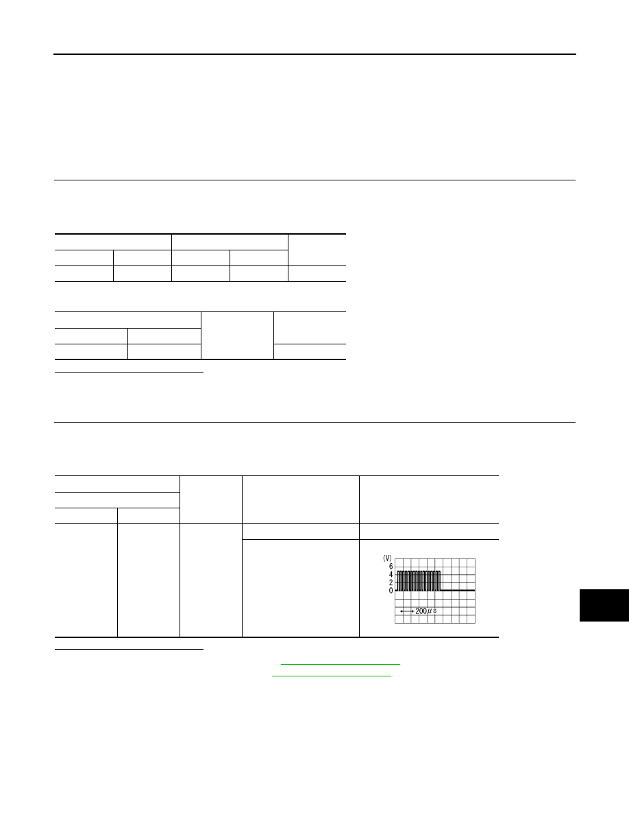
CHECK RGB AREA (YS) SIGNAL

1.

Connect front display unit connector and AV control unit connector.

2.

Turn ignition switch ON.

3.

Check signal between front display unit harness connector and ground.

Is the inspection result normal?

YES

>> Replace front display unit. Refer to 

AV-138, "Exploded View"

.

NO

>> Replace AV control unit. Refer to 

AV-136, "Exploded View"

.

Front display unit

AV control unit

Continuity

Connector

Terminal

Connector

Terminal

M194

9

M202

40

Existed

Front display unit

Ground

Continuity

Connector

Terminal

M194

9

Not existed

(+)

(

)

Condition

Reference value

(Approx.)

Front display unit

Connector

Terminal

M194

9

Ground

At RGB image is displayed

5.0 V

At AUX image is displayed

PKIB4948J

AV-110

< DTC/CIRCUIT DIAGNOSIS >

[WITHOUT NAVIGATION]

HORIZONTAL SYNCHRONIZING (HP) SIGNAL CIRCUIT

HORIZONTAL SYNCHRONIZING (HP) SIGNAL CIRCUIT

Description

INFOID:0000000005246822

In composite image (AUX image, camera image), transmit the vertical synchronizing (VP) signal and horizon-
tal synchronizing (HP) signal from front display unit to AV control unit so as to synchronize the RGB images
displayed with AV control unit such as the image quality adjusting menu, etc.

Diagnosis Procedure

INFOID:0000000005246823

1.

CHECK CONTINUITY HORIZONTAL SYNCHRONIZING (HP) SIGNAL CIRCUIT

1.

Turn ignition switch OFF.

2.

Disconnect front display unit connector and AV control unit connector.

3.

Check continuity between front display unit harness connector and AV control unit harness connector.

4.

Check continuity between front display unit harness connector and ground.

Is the inspection result normal?

YES

>> GO TO 2.

NO

>> Repair harness or connector.

2.

CHECK HORIZONTAL SYNCHRONIZING (HP) SIGNAL

1.

Connect front display unit connector and AV control unit connector.

2.

Turn ignition switch ON.

3.

Check signal between front display unit harness connector and ground.

Is the inspection result normal?

YES

>> Replace AV control unit. Refer to 

AV-136, "Exploded View"

.

NO

>> Replace front display unit. Refer to 

AV-136, "Exploded View"

.

Front display unit

AV control unit

Continuity

Connector

Terminal

Connector

Terminal

M194

8

M202

38

Existed

Front display unit

Ground

Continuity

Connector

Terminal

M194

8

Not existed

(+)

(

)

Reference value

Front display unit

Connector

Terminal

M194

8

Ground

SKIB3601E

AV

VERTICAL SYNCHRONIZING (VP) SIGNAL CIRCUIT

AV-111

< DTC/CIRCUIT DIAGNOSIS >

[WITHOUT NAVIGATION]

C

D

E

F

G

H

I

J

K

L

M

B

A

O

P

VERTICAL SYNCHRONIZING (VP) SIGNAL CIRCUIT

Description

INFOID:0000000005246824

In composite image (AUX image, camera image), transmit the vertical synchronizing (VP) signal and horizon-
tal synchronizing (HP) signal from front display unit to AV control unit so as to synchronize the RGB images
displayed with AV control unit such as the image quality adjusting menu, etc.

Diagnosis Procedure

INFOID:0000000005246825

1.

CHECK CONTINUITY VERTICAL SYNCHRONIZING (VP) SIGNAL CIRCUIT

1.

Turn ignition switch OFF.

2.

Disconnect front display unit connector and AV control unit connector.

3.

Check continuity between front display unit harness connector and AV control unit harness connector.

4.

Check continuity between front display unit harness connector and ground.

Is the inspection result normal?

YES

>> GO TO 2.

NO

>> Repair harness or connector.

2.

CHECK VERTICAL SYNCHRONIZING (VP) SIGNAL

1.

Connect front display unit connector and AV control unit connector.

2.

Turn ignition switch ON.

3.

Check signal between front display unit harness connector and ground.

Is the inspection result normal?

YES

>> Replace AV control unit. Refer to 

AV-136, "Exploded View"

.

NO

>> Replace front display unit. Refer to 

AV-136, "Exploded View"

.

Front display unit

AV control unit

Continuity

Connector

Terminal

Connector

Terminal

M194

20

M202

50

Existed

Front display unit

Ground

Continuity

Connector

Terminal

M194

20

Not existed

(+)

(

)

Reference value

Front display unit

Connector

Terminal

M194

20

Ground

SKIB3598E

AV-112

< DTC/CIRCUIT DIAGNOSIS >

[WITHOUT NAVIGATION]

CAMERA IMAGE SIGNAL CIRCUIT

CAMERA IMAGE SIGNAL CIRCUIT

Description

INFOID:0000000005528978

• AV control unit outputs camera power supply to rear view camera and inputs rear view camera image signal

from rear view camera when the reverse signal is input.  

• The AV control unit that inputs the camera image signal transmits the camera image signal to the front dis-

play unit.

Diagnosis Procedure

INFOID:0000000005528979

1.

CHECK CONTINUITY CAMERA POWER SUPPLY CIRCUIT

1.

Turn ignition switch OFF.

2.

Disconnect AV control unit connector and rear view camera connector.

3.

Check continuity between AV control unit harness connector and rear view camera harness connector.

4.

Check continuity between AV control unit harness connector and ground.

Is inspection result normal?

YES

>> GO TO 2.

NO

>> Repair harness or connector.

2.

CHECK VOLTAGE CAMERA POWER SUPPLY

1.

Connect AV control unit connector and rear view camera connector.

2.

Turn ignition switch ON.

3.

Shift the selector lever to “R”.

4.

Check voltage between AV control unit harness connector and ground.

Is inspection result normal?

YES

>> GO TO 3.

NO

>> Replace AV control unit. Refer to 

AV-136, "Exploded View"

.

3.

CHECK CONTINUITY CAMERA IMAGE SIGNAL CIRCUIT

1.

Turn ignition switch OFF.

2.

Disconnect AV control unit connector and rear view camera connector.

3.

Check continuity between AV control unit harness connector and rear view camera harness connector.

4.

Check continuity between AV control unit harness connector and ground.

AV control unit

Rear view camera

Continuity

Connector

Terminal

Connector

Terminal

M203

73

D121

1

Existed

AV control unit

Ground

Continuity

Connector

Terminal

M203

73

Not existed

(+)

(

)

Condition

Voltage

(Approx.)

AV control unit

Connector

Terminal

M203

73

Ground

Shift position is “R”.

6.0 V

AV control unit

Rear view camera

Continuity

Connector

Terminal

Connector

Terminal

M203

62

D121

3

Existed


Content   ..  82  83  84  85   ..