Infiniti FX35, FX50 (S51). Manual - part 68
AV
FRONT DISPLAY UNIT
AV-45
< ECU DIAGNOSIS INFORMATION >
[WITHOUT NAVIGATION]
C
D
E
F
G
H
I
J
K
L
M
B
A
O
P
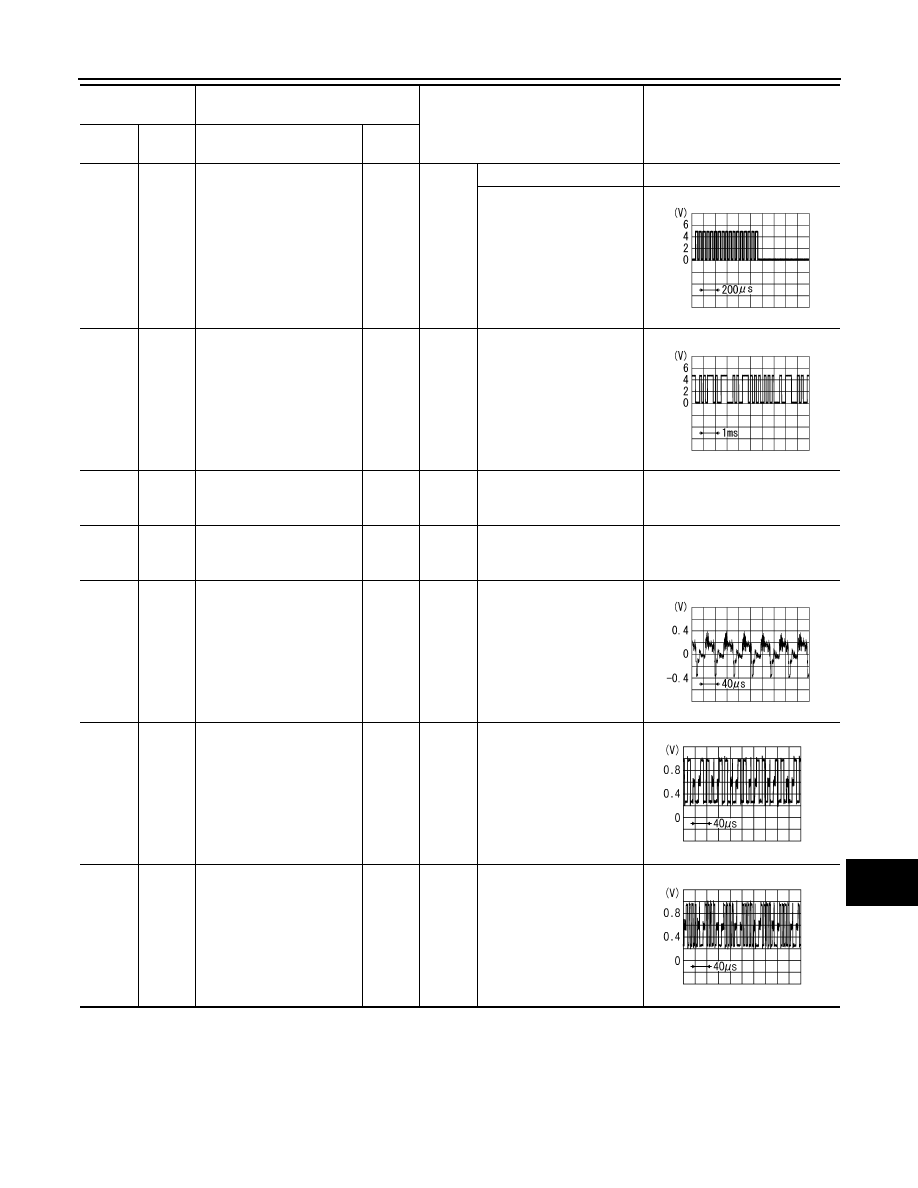
9
(B)
Ground
RGB area (YS) signal
Input
Ignition
switch
ON
At RGB image is displayed.
5.0 V
At AUX image is displayed.
11
(Y)
Ground
Communication signal
(CONT
→
DISP)
Input
Ignition
switch
ON
When adjusting display
brightness.
13
(BR)
Ground
Inverter ground
—
Ignition
switch
ON
—
0 V
14
(LG)
Ground
Signal ground
—
Ignition
switch
ON
—
0 V
15
(SB)
Ground
Composite image signal
Input
Ignition
switch
ON
At camera image is dis-
played.
17
(B)
Ground
RGB signal (R: red)
Input
Ignition
switch
ON
Start Confirmation/Adjust-
ment mode, and then dis-
play color bar by selecting
“Color Spectrum Bar” on
Display Diagnosis screen.
18
(R)
Ground
RGB signal (B: blue)
Input
Ignition
switch
ON
Start Confirmation/Adjust-
ment mode, and then dis-
play color bar by selecting
“Color Spectrum Bar” on
Display Diagnosis screen.
Terminal
(Wire color)
Description
Condition
Reference value
(Approx.)
+
–
Signal name
Input/
Output
PKIB4948J
PKIB5039J
SKIB2251J
JSNIA1029ZZ
JSNIA1031ZZ