Infiniti FX35, FX50 (S51). Manual - part 63
AV
DIAGNOSIS SYSTEM (AV CONTROL UNIT)
AV-25
< SYSTEM DESCRIPTION >
[WITHOUT NAVIGATION]
C
D
E
F
G
H
I
J
K
L
M
B
A
O
P
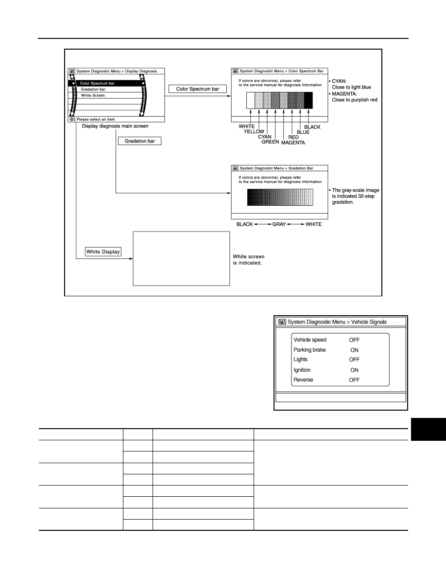
Display Diagnosis
Vehicle Signals
A comparison check can be made of each actual vehicle signal and
the signals recognized by the system.
JSNIA2233GB
JSNIA0149GB
Diagnosis item
Display
Vehicle status
Remarks
Vehicle speed
ON
Vehicle speed > 0 km/h (0 MPH)
Changes in indication may be delayed. This is normal.
OFF
Vehicle speed = 0 km/h (0 MPH)
Parking brake
ON
Parking brake is applied.
OFF
Parking brake is released.
Lights
ON
Light switch ON
—
OFF
Light switch OFF
Ignition
ON
Ignition switch ON
—
OFF
Ignition switch in ACC position