Infiniti FX35, FX50 (S51). Manual - part 6


  Index      Infiniti     Infiniti FX35, FX50 (S51) - service repair manual 2010 year


Search            


Content   ..  4  5  6  7   ..


Infiniti FX35, FX50 (S51). Manual - part 6


ADP-16

< SYSTEM DESCRIPTION >

AUTOMATIC DRIVE POSITIONER SYSTEM

AUTOMATIC DRIVE POSITIONER SYSTEM : Component Description

INFOID:0000000005249626

CONTROL UNITS

INPUT PARTS

Switches

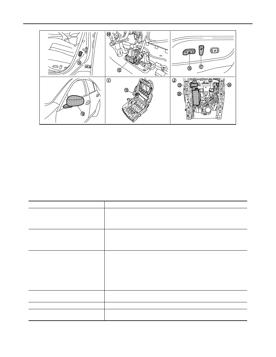
14. Front door switch (driver side) B16

15. A/T shift selector (detention switch) 

M137

16. Sliding, lifting switch

 (Power seat switch B459)

17. Reclining switch (power seat switch 

B459)

18.  Door mirror (driver side) D3

19. Reclining motor B454

20.  Driver seat control unit B451, B452

21. Lifting motor (front) B455

22. Lifting motor (rear) B456

23. Sliding motor B461

24. Sliding sensor B453

H.

View with center console assembly 
removed

I.

View with seat cushion pad and seat-
back pad removed

J.

Backside of the seat cushion

JMJIA1962ZZ

Item

Function

Driver seat control unit

• Main units of automatic drive positioner system
• It is connected to the CAN.
• It communicates with the automatic drive positioner control via UART communi-

cation.

Automatic drive positioner control unit

• It communicates with the driver seat control unit via UART communication.
• Perform various controls with the instructions of driver seat control unit.
• Perform the controls of the tilt & telescopic, door mirror and the seat memory 

switch. 

BCM

Transmit the following status to the driver seat control unit via CAN communication.
• Driver door: OPEN/CLOSE
• Ignition switch position: ACC/ON
• Door lock: UNLOCK (with Intelligent Key or driver side door request switch oper-

ation)

• Key  ID
• Key switch: Insert/Pull out Intelligent Key
• Starter: CRANKING/OTHER

Unified meter and A/C amp.

Transmit the vehicle speed signal to the driver seat control unit via CAN communi-
cation.

AV control unit

The setting change of auto drive positioner system can be performed on the display.

TCM

Transmit the shift position signal (P range) to the driver seat control unit via CAN 
communication.

AUTOMATIC DRIVE POSITIONER SYSTEM

ADP-17

< SYSTEM DESCRIPTION >

C

D

E

F

G

H

I

K

L

M

A

B

ADP

N

O

P

Sensors

OUTPUT PARTS

MANUAL FUNCTION

Item

Function

Key slot

The key switch is installed to detect the key inserted/removed status.

Front door switch (driver side)

Detect front door (driver side) open/close status. 

A/T shift selector (detention switch)

Detect the P range position of A/T selector lever.

Set switch

The registration and system setting can be performed with its operation.

Memory switch 1/2

The registration and operation can be performed with its operation.

Power seat switch

The following switch is installed.
• Reclining switch
• Lifting switch (front)
• Lifting switch (rear)
• Sliding switch
The specific parts can be operated with the operation of each switch.

Tilt & telescopic switch

The following switch is installed.
• Tilt switch
• Telescopic switch
The specific parts can be operated with the operation of each switch.

Door mirror remote control switch

The following switch is installed.
• Mirror switch
• Changeover switch
The specific parts can be operated with the operation of each switch.

Item

Function

Door mirror sensor 
(driver side/passenger side)

Detect the up/down and left/right position of outside mirror face.

Tilt and telescopic sensor

Detect the up/down and front/rear position of steering column.

Lifting sensor (front)

Detect the up/down position of seat lifting (front).

Lifting sensor (rear)

Detect the up/down position of seat lifting (rear).

Reclining sensor

Detect the tilt of seatback.

Sliding sensor

Detect the front/rear position of seat.

Item

Function

Door mirror motor
(driver side/passenger side)

Move the outside mirror face upward/downward and leftward/rightward.

Tilt and telescopic motor

Move the steering column upward/downward and forward/backward.

Lifting motor (front)

Move the seat lifting (front) upward/downward.

Lifting motor (rear)

Move the seat lifting (rear) upward/downward.

Reclining motor

Tilt and raise up the seatback.

Sliding motor

Slide the seat forward/backward.

Memory indicator

Illuminates or flashes according to the registration/operation status.

ADP-18

< SYSTEM DESCRIPTION >

AUTOMATIC DRIVE POSITIONER SYSTEM

MANUAL FUNCTION : System Diagram

INFOID:0000000005249627

MANUAL FUNCTION : System Description

INFOID:0000000005249628

OUTLINE

The driving position (seat, steering column and door mirror position) can be adjusted manually with power seat
switch, tilt & telescopic switch and door mirror remote control switch.

OPERATION PROCEDURE

1.

Turn ignition switch ON.

2.

Operate power seat switch, tilt & telescopic switch or door mirror remote control switch.

3.

The driver seat, steering column or door mirror operates according to the operation of each switch.

DETAIL FLOW

Seat

Tilt & Telescopic

JMJIA2302GB

Order

Input

Output

Control unit condition

1

Power seat switch
(sliding, lifting, reclin-
ing)

The power seat switch signal is inputted to the driver seat control 
unit when the power seat switch is operated.

2

Motors
(sliding, lifting, reclin-
ing)

The driver seat control unit outputs signals to each motor accord-
ing to the power seat switch input signal.

Order

Input

Output

Control unit condition

1

Tilt & telescopic switch

The tilt & telescopic switch signal is inputted to the automatic 
drive positioner control unit when the tilt & telescopic switch is op-
erated.

AUTOMATIC DRIVE POSITIONER SYSTEM

ADP-19

< SYSTEM DESCRIPTION >

C

D

E

F

G

H

I

K

L

M

A

B

ADP

N

O

P

*: Tilt does not operates upward when tilt sensor volume is less than 1.2 V, tilt does not operate downward when the sensor value is big-
ger than 3.4 V. Telescopic does not operates backward when telescopic sensor value is less than 0.8 V, telescopic does not operate for-
ward when the sensor value is bigger than 3.4 V.

Door Mirror

NOTE:
The door mirrors can be operated manually when ignition switch is in either ACC or ON position. The ignition
switch signal (ACC/ON) is transmitted from BCM to the driver seat control unit via CAN communication and
from the driver seat control unit to the automatic drive positioner control unit via UART communication.

2

Motors
(Tilt, telescopic)

The automatic drive positioner control unit actuates each motor 
according to the operation of the tilt & telescopic switch.

3

Sensors
(Tilt, telescopic)

The automatic drive positioner control unit recognizes any oper-
ation limit of each actuator via each sensor and will not operate 
the actuator anymore at that time.*

Order

Input

Output

Control unit condition

Order

Input

Output

Control unit condition

1

Door mirror remote 
control switch

The door mirror remote control switch signal is inputted to the au-
tomatic drive positioner control unit when the door mirror remote 
control switch is operated.

2

Motors
(Door mirror motor)

The automatic drive positioner control unit actuates each motor 
according to the operation of the door mirror remote control switch.


Content   ..  4  5  6  7   ..