Index Infiniti Infiniti EX35 - service repair manual 2008 year
Search
Content .. 938 939 940 941 ..
Infiniti EX35. Manual - part 940
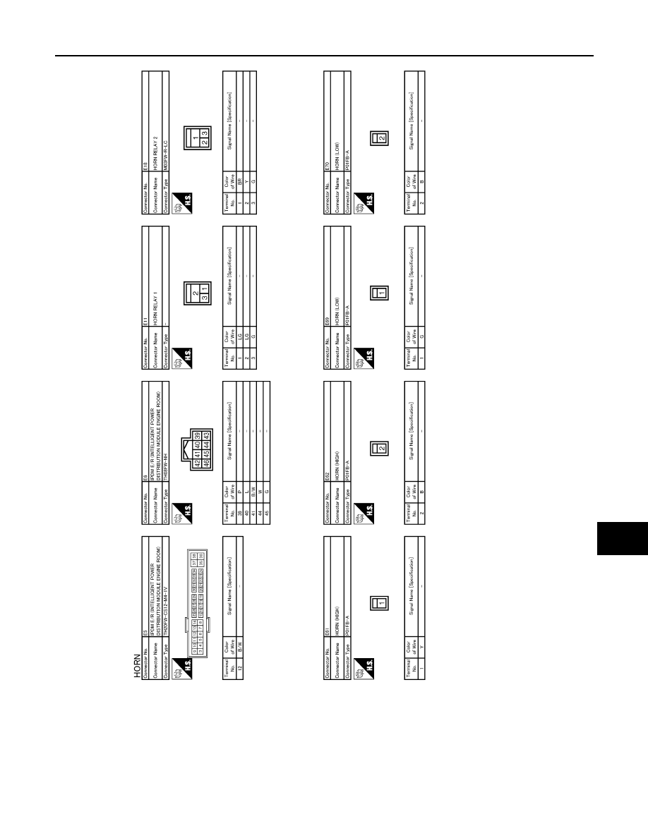
HORN
HRN-3
< COMPONENT DIAGNOSIS >
C
D
E
F
G
H
I
J
K
M
A
B
HRN
N
O
P
JCLWM1306GB