Infiniti EX35. Manual - part 922


  Index      Infiniti     Infiniti EX35 - service repair manual 2008 year


Search            


Content   ..  920  921  922  923   ..


Infiniti EX35. Manual - part 922


HAC-84

< COMPONENT DIAGNOSIS >

[AUTOMATIC AIR CONDITIONER]

BLOWER MOTOR

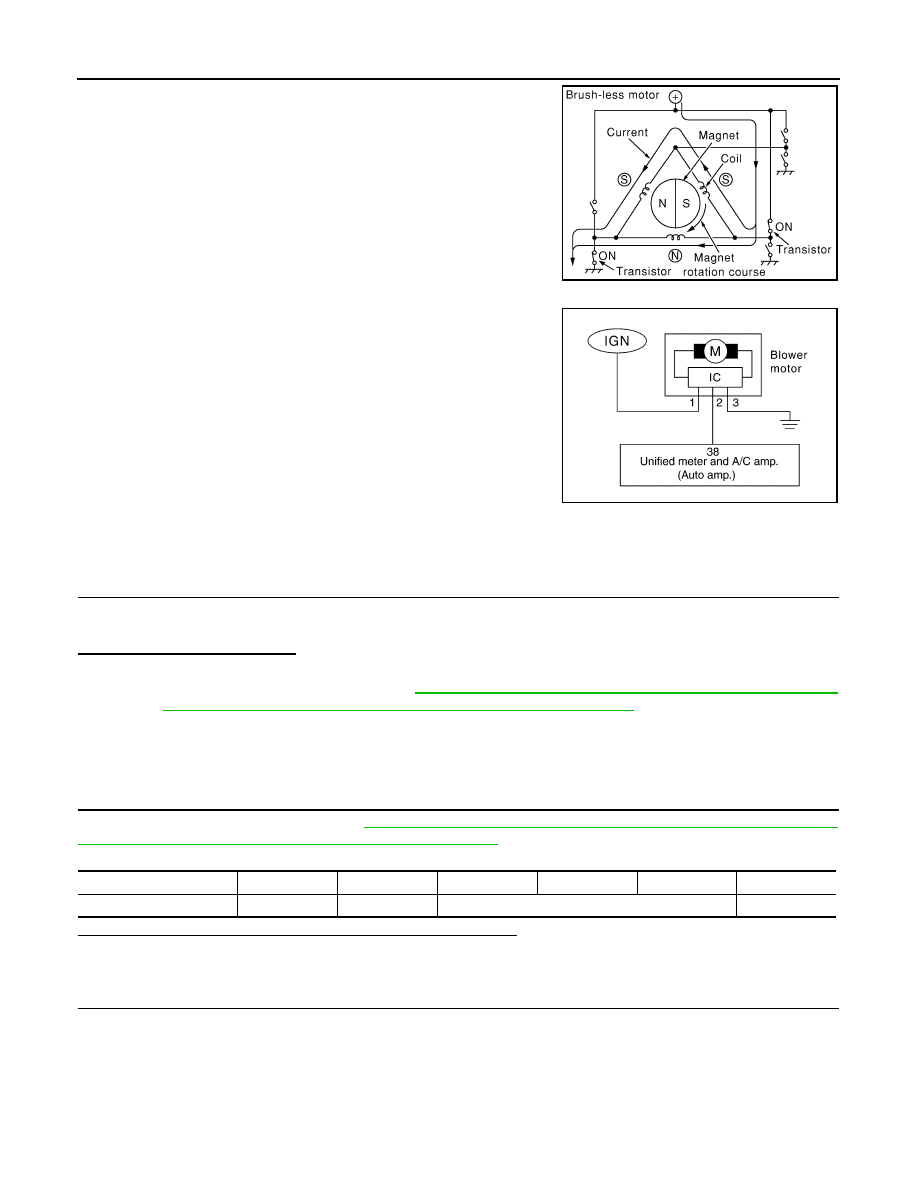
Blower motor circuit

WITH LEFT AND RIGHT VENTILATION TEMPERATURE SEPARATELY CONTROL 
SYSTEM : Component Function Check

INFOID:0000000003545620

1.

CONFIRM SYMPTOM BY PERFORMING THE FOLLOWING OPERATIONAL CHECK

1.

Press fan (UP: +) switch. Blower should operate on low speed.

2.

Press fan (UP: +) switch, and continue checking blower speed and fan symbol until all speeds checked.

Is the inspection result normal?

YES

>> END.

NO

>> Go to diagnosis procedure. Refer to 

HAC-84, "WITH LEFT AND RIGHT VENTILATION TEMPER-

ATURE SEPARATELY CONTROL SYSTEM : Diagnosis Procedure"

.

WITH LEFT AND RIGHT VENTILATION TEMPERATURE SEPARATELY CONTROL 
SYSTEM : Diagnosis Procedure

INFOID:0000000003545621

1.

PERFORM SELF-DIAGNOSIS STEP-4

Perform self-diagnosis STEP-4. Refer to 

HAC-63, "WITH LEFT AND RIGHT VENTILATION TEMPERATURE

SEPARATELY CONTROL SYSTEM : Diagnosis Description"

, see Nos. 1 to 5.

Does blower motor speed change according to each code No.?

YES

>> END.

NO

>> GO TO 2.

2.

CHECK POWER SUPPLY FOR BLOWER MOTOR

1.

Disconnect blower motor connector.

2.

Turn ignition switch ON.

3.

Check voltage between blower motor harness connector and ground.

ZHA152H

RJIA4071E

Code  No.

41

42

43

44

45

46

Blower motor duty ratio

37%

91%

65%

91%

BLOWER MOTOR

HAC-85

< COMPONENT DIAGNOSIS >

[AUTOMATIC AIR CONDITIONER]

C

D

E

F

G

H

J

K

L

M

A

B

HAC

N

O

P

Is the inspection result normal?

YES

>> GO TO 3.

NO

>> GO TO 6.

3.

CHECK BLOWER MOTOR GROUND CIRCUIT

1.

Turn ignition switch OFF.

2.

Check continuity between blower motor harness connector and ground.

Is the inspection result normal?

YES

>> GO TO 4.

NO

>> Repair harness or connector.

4.

CHECK CIRCUIT CONTINUITY BETWEEN BLOWER MOTOR AND UNIFIED METER AND A/C AMP.

1.

Disconnect unified meter and A/C amp. connector.

2.

Check continuity between blower motor harness connector and unified meter and A/C amp. harness con-
nector.

3.

Check continuity between blower motor harness connector and ground.

Is the inspection result normal?

YES

>> GO TO 5.

NO

>> Repair harness or connector.

5.

CHECK UNIFIED METER AND A/C AMP. OUTPUT SIGNAL

1.

Reconnect blower motor connector and unified meter and A/C amp. connector.

2.

Turn ignition switch ON.

3.

Set MODE switch to VENT position.

(+)

(

)

Voltage

Blower motor

Connector

Terminal

M109

1

Ground

Battery voltage

blower motor

Continuity

Connector

Terminal

M109

3

Ground

Existed

blower motor

Unified meter and A/C amp.

Continuity

Connector

Terminal

Connector

Terminal

M109

2

M66

38

Existed

blower motor

Continuity

Connector

Terminal

M109

2

ground

Not existed

HAC-86

< COMPONENT DIAGNOSIS >

[AUTOMATIC AIR CONDITIONER]

BLOWER MOTOR

4.

Change fan speed from Lo to Hi, and check duty ratios between blower motor harness connector and
ground by using an oscilloscope. Normal terminal 2 drive signal duty ratios are shown in the table below.

Is the inspection result normal?

YES

>> Replace blower motor after confirming the fan air flow does not change.

NO

>> Replace unified meter and A/C amp.

6.

CHECK POWER VOLTAGE OF BLOWER RELAY

1.

Turn ignition switch OFF.

2.

Remove blower relay. Refer to 

PG-98, "Fuse, Connector and Terminal Arrangement"

.

3.

Turn ignition switch ON.

4.

Check the voltage between blower relay fuse block terminals and ground. Refer to 

PG-96, "Description"

for relay terminal assignment.

Is the inspection result normal?

YES

>> GO TO 7.

NO

>> Check ignition power supply circuit. Refer to 

PG-51, "Wiring Diagram - IGNITION POWER SUP-

PLY -"

.

7.

CHECK BLOWER RELAY

1.

Turn ignition switch OFF.

2.

Install blower relay. Refer to 

PG-98, "Fuse, Connector and Terminal Arrangement"

.

3.

Check operation sound of the blower relay after switching ignition switch ON.

Is the inspection result normal?

YES

>> GO TO 8.

NO

>> Replace blower relay.

8.

CHECK FUSE

Check fuse 15A [Nos 21 and 22, located in the fuse block (J/B). Refer to 

PG-98, "Fuse, Connector and Termi-

nal Arrangement"

.

Is the inspection result normal?

YES

>> Repair harness or connector.

NO

>> Be sure to eliminate cause of malfunction before installing new fuse.

WITH LEFT AND RIGHT VENTILATION TEMPERATURE SEPARATELY CONTROL 

JSIIA0068GB

(+)

(

)

Voltage

Blower relay

1

Ground

Battery voltage

3

BLOWER MOTOR

HAC-87

< COMPONENT DIAGNOSIS >

[AUTOMATIC AIR CONDITIONER]

C

D

E

F

G

H

J

K

L

M

A

B

HAC

N

O

P

SYSTEM : Component Inspection

INFOID:0000000003545622

1.

CHECK BLOWER MOTOR

1.

Remove blower motor (1). Refer to 

VTL-33, "Exploded View"

.

2.

Confirm smooth rotation of the blower motor.

Is the inspection result normal?

YES

>> END.

NO

>> Replace blower motor.

JSIIA1074ZZ


Content   ..  920  921  922  923   ..