Infiniti EX35. Manual - part 920


  Index      Infiniti     Infiniti EX35 - service repair manual 2008 year


Search            


Content   ..  918  919  920  921   ..


Infiniti EX35. Manual - part 920


HAC-76

< COMPONENT DIAGNOSIS >

[AUTOMATIC AIR CONDITIONER]

AIR MIX DOOR MOTOR

Check installation of air mix door motor (driver side). Refer to 

VTL-43, "Exploded View"

.

Is it installed normally?

YES

>> GO TO 4.

NO

>> Repair or replace air mix door motor (driver side).

4.

CHECK POWER SUPPLY FOR AIR MIX DOOR MOTOR (DRIVER SIDE)

Check voltage between air mix door motor (driver side) harness connector and ground.

Is the inspection result normal?

YES

>> GO TO 5.

NO

>> Repair harness or connector.

5.

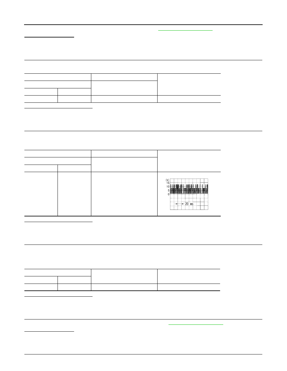
CHECK SIGNAL FOR AIR MIX DOOR MOTOR (DRIVER SIDE)

Confirm A/C LAN signal between air mix door motor (driver side) harness connector and ground using an
oscilloscope.

Is the inspection result normal?

YES

>> GO TO 6.

NO

>> Repair harness or connector.

6.

CHECK AIR MIX DOOR MOTOR (DRIVER SIDE) GROUND CIRCUIT

1.

Turn ignition switch OFF.

2.

Disconnect air mix door motor (driver side) connector.

3.

Check continuity between air mix door motor (driver side) harness connector and ground.

Is the inspection result normal?

YES

>> Replace air mix door motor (driver side).

NO

>> Repair harness or connector.

7.

CHECK INSTALLATION OF AIR MIX DOOR MOTOR (PASSENGER SIDE)

Check installation of air mix door motor (passenger side). Refer to 

VTL-43, "Exploded View"

.

Is it installed normally?

YES

>> GO TO 8.

NO

>> Repair or replace air mix door motor (passenger side).

8.

CHECK POWER SUPPLY FOR AIR MIX DOOR MOTOR (PASSENGER SIDE)

(+)

(

)

Voltage

Air mix door motor (driver side)

Connector

Terminal

M252

1

Ground

Battery voltage

(+)

(

)

Voltage

Air mix door motor (driver side)

Connector

Terminal

M252

3

Ground

SJIA1453J

Air mix door motor (driver side)

Continuity

Connector

Terminal

M252

2

Ground

Existed

AIR MIX DOOR MOTOR

HAC-77

< COMPONENT DIAGNOSIS >

[AUTOMATIC AIR CONDITIONER]

C

D

E

F

G

H

J

K

L

M

A

B

HAC

N

O

P

Check voltage between air mix door motor (passenger side) harness connector and ground.

Is the inspection result normal?

YES

>> GO TO 9.

NO

>> Repair harness or connector.

9.

CHECK SIGNAL FOR AIR MIX DOOR MOTOR (PASSENGER SIDE)

Confirm A/C LAN signal between air mix door motor (passenger side) harness connector and ground using an
oscilloscope.

Is the inspection result normal?

YES

>> GO TO 10.

NO

>> Repair harness or connector.

10.

CHECK AIR MIX DOOR MOTOR (PASSENGER SIDE) GROUND CIRCUIT

1.

Turn ignition switch OFF.

2.

Disconnect air mix door motor (passenger side) connector.

3.

Check continuity between air mix door motor (passenger side) harness connector and ground.

Is the inspection result normal?

YES

>> Replace air mix door motor (passenger side).

NO

>> Repair harness or connector.

(+)

(

)

Voltage

Air mix door motor (passenger side)

Connector

Terminal

M255

1

Ground

Battery voltage

(+)

(

)

Voltage

Air mix door motor (passenger side)

Connector

Terminal

M255

3

Ground

SJIA1453J

Air mix door motor (passenger side)

Continuity

Connector

Terminal

M255

2

Ground

Existed

HAC-78

< COMPONENT DIAGNOSIS >

[AUTOMATIC AIR CONDITIONER]

INTAKE DOOR MOTOR

INTAKE DOOR MOTOR

Description

INFOID:0000000003545612

COMPONENT DESCRIPTION

Intake Door Motor

The intake door motor (1) is attached to the blower unit. It rotates so
that air is drawn from inlets set by the unified meter and A/C amp.
Motor rotation is conveyed to a lever which activates the intake door.

Component Function Check

INFOID:0000000003545613

1.

CONFIRM SYMPTOM BY PERFORMING THE FOLLOWING OPERATIONAL CHECK

1.

Press intake switch.

2.

REC indicator turns ON.

3.

Listen for intake door position change (Slight change of blower sound can be heard.).

4.

Press intake switch again.

5.

FRE indicator turns ON.

Is the inspection result normal?

YES

>> END.

NO

>> Go to diagnosis procedure. Refer to 

HAC-78, "Diagnosis Procedure"

.

Diagnosis Procedure

INFOID:0000000003545614

1.

PERFORM SELF-DIAGNOSIS STEP-2

Perform self-diagnosis STEP-2. Refer to 

HAC-57, "WITHOUT LEFT AND RIGHT VENTILATION TEMPERA-

TURE SEPARATELY CONTROL SYSTEM : Diagnosis Description"

 (Without left and right ventilation tempera-

ture separately control system) or 

HAC-63, "WITH LEFT AND RIGHT VENTILATION TEMPERATURE

SEPARATELY CONTROL SYSTEM : Diagnosis Description"

 (With left and right ventilation temperature sepa-

rately control system), see Nos. 1 to 2.

Does code No. 20 appear on the display?

YES

>> GO TO 2.

NO

>> Go to appropriate malfunctioning sensor circuit. Refer to 

HAC-57, "WITHOUT LEFT AND RIGHT

VENTILATION TEMPERATURE SEPARATELY CONTROL SYSTEM : Diagnosis Description"

(Without left and right ventilation temperature separately control system) or 

HAC-63, "WITH LEFT

AND RIGHT VENTILATION TEMPERATURE SEPARATELY CONTROL SYSTEM : Diagnosis
Description"

 (With left and right ventilation temperature separately control system), see No. 11.

2.

PERFORM SELF-DIAGNOSIS STEP-4

Perform self-diagnosis STEP-4. Refer to 

HAC-57, "WITHOUT LEFT AND RIGHT VENTILATION TEMPERA-

TURE SEPARATELY CONTROL SYSTEM : Diagnosis Description"

 (Without left and right ventilation tempera-

ture separately control system) or 

HAC-63, "WITH LEFT AND RIGHT VENTILATION TEMPERATURE

SEPARATELY CONTROL SYSTEM : Diagnosis Description"

 (With left and right ventilation temperature sepa-

rately control system), see Nos. 1 to 5.
Is it operated normally?

YES

>> END.

NO

>> GO TO 3.

3.

CHECK INTAKE DOOR CONTROL LINKAGE

:

Vehicle front

JSIIA0007GB

INTAKE DOOR MOTOR

HAC-79

< COMPONENT DIAGNOSIS >

[AUTOMATIC AIR CONDITIONER]

C

D

E

F

G

H

J

K

L

M

A

B

HAC

N

O

P

Check intake door control linkage.

Is it installed normally?

YES

>> GO TO 4.

NO

>> Repair or adjust control linkage.

4.

CHECK POWER SUPPLY FOR INTAKE DOOR MOTOR

Check voltage between intake door motor harness connector and ground.

Is the inspection result normal?

YES

>> GO TO 5.

NO

>> Repair harness or connector.

5.

CHECK SIGNAL FOR INTAKE DOOR MOTOR

Confirm A/C LAN signal between intake door motor harness connector and ground using an oscilloscope.

Is the inspection result normal?

YES

>> GO TO 6.

NO

>> Repair harness or connector.

6.

CHECK INTAKE DOOR MOTOR GROUND CIRCUIT

1.

Turn ignition switch OFF.

2.

Disconnect intake door motor connector.

3.

Check continuity between intake door motor harness connector and ground.

Is the inspection result normal?

YES

>> Replace intake door motor.

NO

>> Repair harness or connector.

(+)

(

)

Voltage

Intake door motor

Connector

Terminal

M254

1

Ground

Battery voltage

(+)

(

)

Voltage

Intake door motor

Connector

Terminal

M254

3

Ground

SJIA1453J

Intake door motor

Continuity

Connector

Terminal

M254

2

Ground

Existed


Content   ..  918  919  920  921   ..